Subsystem
Positioning
and
Cabling
I/O
subsystems
can
be
installed
in
a
standard
19-inch
EIA
rack
in
any
location.
The
cables
that
connect
the
subsystems
allow
some
flexibility
in
drawer
placement,
but
the
I/O
subsystems
should
be
located
above
the
processor
subsystem
to
which
they
are
connected
in
the
same
rack.
Up
to
eight
I/O
subsystems
can
be
connected
to
a
processor
subsystem.
Use
the
following
guidelines:
v
Each
I/O
subsystem
connects
to
the
processor
subsystem
using
one
system
power
control
network
(SPCN)
cable
loop.
v
Each
I/O
subsystem
connects
to
the
processor
subsystem
using
one
or
more
remote
I/O
(RIO)
cable
loops.
v
Lowest
cost
configurations
allow
up
to
four
I/O
subsystems
connected
to
the
processor
subsystem
using
a
single
RIO
loop.
v
Optimum
performance
is
achieved
when
each
I/O
drawer
is
connected
to
the
processor
subsystem
through
its
own
RIO
loop.
Note:
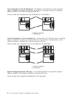
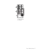
The
cabling
illustrations
in
this
section
show
examples
of
how
the
cabling
between
a
processor
subsystem
and
connected
I/O
subsystems
can
be
done.
The
example
illustrations
show
the
logical
connections
of
SPCN
and
RIO
cables.
Your
system’s
cables
might
be
physically
connected
in
a
different
way
from
these
examples.
SPCN
Cabling
I/O
subsystem
SPCN
cables
are
connected
to
the
processor
subsystem
unit
in
a
loop
configuration.
The
SPCN
cables
are
connected
in
a
loop
so
that
the
system
has
two
paths
to
each
I/O
subsystem.
Up
to
eight
I/O
subsystems
are
supported
on
one
SPCN
loop.
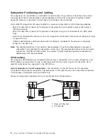
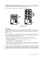
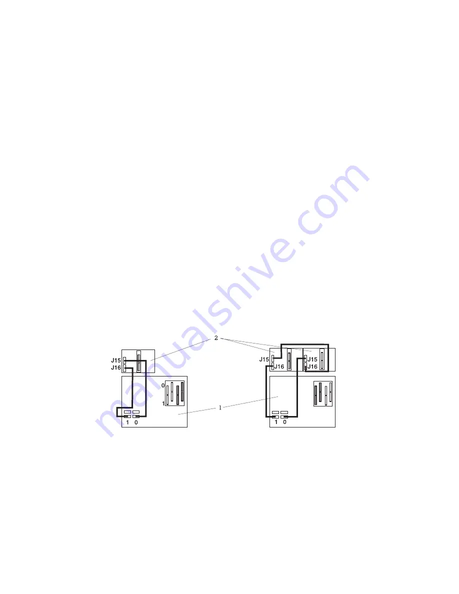
One
I/O
Subsystem,
Two
I/O
Subsystems:
The
illustrations
on
the
left
show
one
I/O
subsystem
connected
to
the
processor
subsystem.
The
illustrations
on
the
right
show
two
I/O
subsystems
connected
to
the
processor
subsystem
using
one
SPCN
loop.
Processor
Subsystem
Connected
to
One
or
Two
Model
D10
I/O
Subsystems:
1
Processor
Subsystem
2
I/O
Subsystem
6
Eserver
pSeries
7311
Model
D10
and
Model
D20
Service
Guide
Содержание eserver pSeries 7311 D10
Страница 1: ...pSeries 7311 Model D10 and Model D20 Service Guide SA38 0627 01 ERserver...
Страница 2: ......
Страница 3: ...pSeries 7311 Model D10 and Model D20 Service Guide SA38 0627 01 ERserver...
Страница 8: ...vi Eserver pSeries 7311 Model D10 and Model D20 Service Guide...
Страница 12: ...x Eserver pSeries 7311 Model D10 and Model D20 Service Guide...
Страница 14: ...xii Eserver pSeries 7311 Model D10 and Model D20 Service Guide...
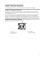
Страница 25: ...1 Processor Subsystem 2 I O Subsystem Chapter 1 Reference Information 9...
Страница 89: ...Chapter 3 Removal and Replacement Procedures 73...
Страница 99: ...2 1 1 Top of Cassette 2 Handle Chapter 3 Removal and Replacement Procedures 83...
Страница 179: ...D10 I O Subsystem Parts continued 1 2 3 4 5 6 7 Chapter 4 Parts Information 163...
Страница 207: ......
Страница 208: ...Printed in USA May 2003 SA38 0627 01...


