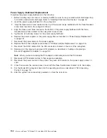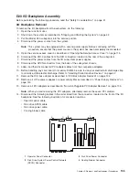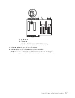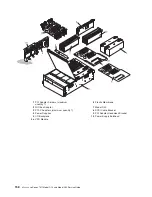
15.
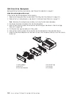
Remove
the
plastic
membrane
from
the
top
of
the
I/O
backplane
by
first
removing
the
five
retaining
screws
that
secure
the
plastic
membrane
to
the
I/O
backplane.
Note:
When
removing
the
plastic
membrane,
slide
the
membrane
under
the
light
pipes
that
identify
the
green
and
amber
power
LEDs.
16.
Remove
the
three
retaining
screws
that
secure
the
front
edge
of
the
I/O
backplane
to
the
subsystem
chassis.
17.
Go
to
the
rear
of
the
subsystem,
and
remove
the
two
retaining
screws
that
secure
the
back
edge
of
the
I/O
backplane
to
the
back
chassis
bulkhead.
Note:
The
two
retaining
screws
that
secure
the
back
edge
of
the
I/O
backplane
to
the
rear
chassis
bulkhead
are
located
just
below
the
left
SPCN
connector
and
the
rack
indicator
connector.
18.
Remove
the
two
retaining
screws
that
secure
the
SCSI
cable
bracket
to
the
subsystem-chassis
bracket.
19.
Remove
the
SCSI
cable
bracket
by
wiggling
it
up
and
down,
then
pulling
it
straight
out
and
away
from
the
PCI
adapter-headstock
bracket
and
the
subsystem
chassis
bracket.
20.
Remove
the
four
retaining
screws
that
secure
the
PCI
adapter-headstock
bracket
to
the
chassis
and
power
supply
bulkhead.
21.
Remove
the
PCI
adapter-headstock
bracket
by
lifting
it
up,
then
out
of
the
subsystem
chassis.
22.
Remove
the
four
retaining
screws
that
secure
the
power-supply
bulkhead
to
the
chassis
23.
Remove
the
power-supply
bulkhead
by
doing
the
following:
a.
Lift
the
slotted
tab
off
the
alignment
pin.
The
slotted
tab
and
alignment
pin
are
located
at
the
bottom
edge
of
the
power-supply
bulkhead.
b.
Move
the
lower
portion
of
the
power-supply
bulkhead
out
and
away
from
the
alignment
pin.
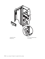
Notes:
1)
Ensure
that
the
back
edge
of
the
power-supply
bulkhead
clears
the
disk
drive
backplane’s
plastic
alignment
pin.
The
disk
drive
backplane’s
plastic
alignment
pin
is
located
on
the
disk
drive-backplane
support
bracket
between
the
power-supply
bulkhead
and
the
PCI
adapter-headstock
bracket.
2)
The
disk
drive
backplane-support
bracket
is
not
shown
in
the
following
illustration;
however,
it
is
easily
located.
This
is
the
bracket
that
secures
the
service
access
cover
to
the
chassis.
It
also
supports
the
disk
drive
backplanes,
cooling
blowers,
power
supply
bulkhead,
and
PCI
adapter
headstock
bracket.
c.
Push
the
power-supply
bulkhead
toward
the
center
of
the
I/O
subsystem
chassis.
Note:
The
upper-right
corner
of
the
power-supply
bulkhead
might
get
caught
on
the
underside
of
the
chassis
support.
If
the
power-supply
bulkhead
gets
caught
on
the
underside
of
the
chassis
support,
wiggle
the
bulkhead
until
it
is
freed
from
under
the
chassis
support.
24.
Remove
the
I/O
backplane
by
sliding
the
backplane
toward
the
front
of
the
I/O
subsystem.
25.
Slowly
lift
the
I/O
backplane
straight
up
and
out
of
the
subsystem.
26.
Locate
the
VPD
module.
156
Eserver
pSeries
7311
Model
D10
and
Model
D20
Service
Guide
Содержание eserver pSeries 7311 D10
Страница 1: ...pSeries 7311 Model D10 and Model D20 Service Guide SA38 0627 01 ERserver...
Страница 2: ......
Страница 3: ...pSeries 7311 Model D10 and Model D20 Service Guide SA38 0627 01 ERserver...
Страница 8: ...vi Eserver pSeries 7311 Model D10 and Model D20 Service Guide...
Страница 12: ...x Eserver pSeries 7311 Model D10 and Model D20 Service Guide...
Страница 14: ...xii Eserver pSeries 7311 Model D10 and Model D20 Service Guide...
Страница 25: ...1 Processor Subsystem 2 I O Subsystem Chapter 1 Reference Information 9...
Страница 89: ...Chapter 3 Removal and Replacement Procedures 73...
Страница 99: ...2 1 1 Top of Cassette 2 Handle Chapter 3 Removal and Replacement Procedures 83...
Страница 179: ...D10 I O Subsystem Parts continued 1 2 3 4 5 6 7 Chapter 4 Parts Information 163...
Страница 207: ......
Страница 208: ...Printed in USA May 2003 SA38 0627 01...

