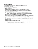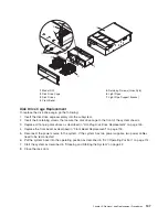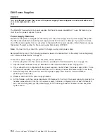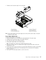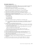
19.
Replace
all
of
the
previously
removed
PCI
adapters
as
described
in
“Adding
or
Replacing
a
Non-Hot-Pluggable
PCI
Adapter”
on
page
132.
Note:
Alternately
reinstall
the
PCI
dividers,
when
reinstalling
the
PCI
adapters.
20.
Reconnect
all
PCI
adapter
cables
to
their
respective
adapters.
21.
Reconnect
the
power
cables
to
the
power
supplies.
22.
Reconnect
the
power
source
to
the
system.
The
green
LED
located
on
the
power
supply
comes
on
solid.
23.
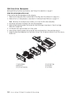
Close
and
then
secure
the
service
access
cover
with
the
three
thumbscrews
located
on
its
back
edge.
24.
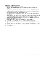
Put
the
Model
D20
subsystem
back
into
the
operating
position
as
described
in
“D20
Operating
Position”
on
page
114.
25.
After
the
system
has
successfully
powered
on,
close
the
rack
doors.
160
Eserver
pSeries
7311
Model
D10
and
Model
D20
Service
Guide
Содержание eserver pSeries 7311 D10
Страница 1: ...pSeries 7311 Model D10 and Model D20 Service Guide SA38 0627 01 ERserver...
Страница 2: ......
Страница 3: ...pSeries 7311 Model D10 and Model D20 Service Guide SA38 0627 01 ERserver...
Страница 8: ...vi Eserver pSeries 7311 Model D10 and Model D20 Service Guide...
Страница 12: ...x Eserver pSeries 7311 Model D10 and Model D20 Service Guide...
Страница 14: ...xii Eserver pSeries 7311 Model D10 and Model D20 Service Guide...
Страница 25: ...1 Processor Subsystem 2 I O Subsystem Chapter 1 Reference Information 9...
Страница 89: ...Chapter 3 Removal and Replacement Procedures 73...
Страница 99: ...2 1 1 Top of Cassette 2 Handle Chapter 3 Removal and Replacement Procedures 83...
Страница 179: ...D10 I O Subsystem Parts continued 1 2 3 4 5 6 7 Chapter 4 Parts Information 163...
Страница 207: ......
Страница 208: ...Printed in USA May 2003 SA38 0627 01...

