4-58
Service Guide
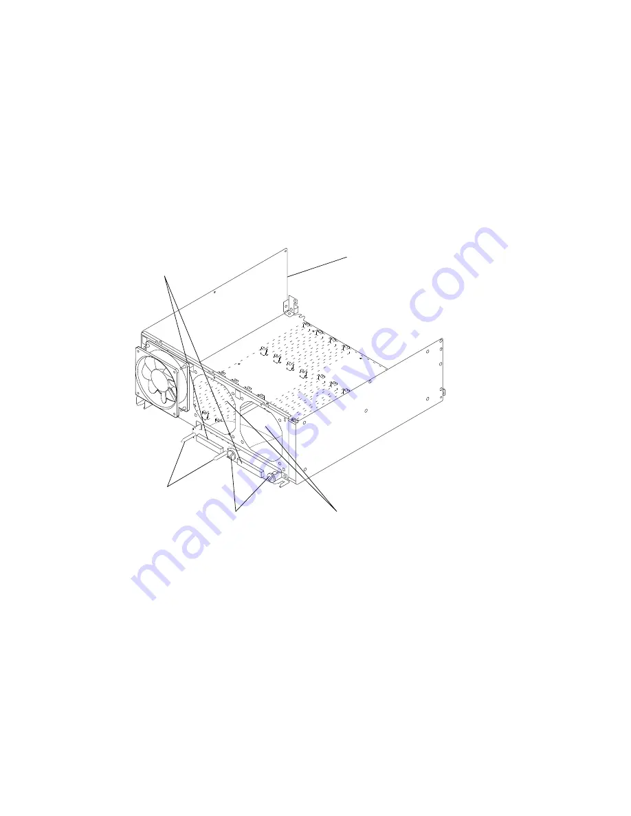
5. Record the location of the flex cable connectors.
6. If you are removing the flex cable connected to the horizontal connector on the I/O card,
remove the two large slotted mounting screws.
If you are removing the flex cable connected to the vertical connector on the I/O card,
remove the two guide pin mounting screws.
Attention: To prevent damage to the pins, do not use pliers to remove the two guide pin
mounting screws, use an open-end wrench.
7. Remove the fan located above the flex cable connector you are removing. Refer to the
“CPU Module Fans” removal procedure on page 4-50.
Guide Pin
Mounting
Screws
Large Slotted
Mounting Screws
Two Fans Are Shown Removed
Flex Cable
Connectors
CPU Module
Содержание 7015-R30
Страница 1: ...7015 Models R30 R40 and R50 CPU Enclosure Installation and Service Guide...
Страница 10: ...x Service Guide...
Страница 14: ...xiv Service Guide...
Страница 34: ...1 20 Service Guide...
Страница 206: ...6 2 Service Guide Detail 1 Front Bezel Front Access Plate and CPU Enclosure 1 2 3 4 5 10 11 12 6 10 11 12 9 7 8...
Страница 210: ...6 6 Service Guide Detail 3 Media Module 1 21 22 2 3 7 6 5 4 13 9 8 20 16 14 10 15 17 11 18 23 24 19 12...
Страница 212: ...6 8 Service Guide Detail 4 CPU Module 1 of 3 17 18 19 3 12 1 2 5 6 4 7 20 21 22 14 8 9 10 16 15 24 25 11 13 23...
Страница 214: ...6 10 Service Guide Detail 5 CPU Module 2 of 3 26 27 29 30 31 32 33 34 28 35...
Страница 216: ...6 12 Service Guide Detail 6 CPU Module 3 of 3 36 37...
Страница 252: ...B 8 Installation and Service Guide...
Страница 288: ...Service Guide D 30...
Страница 299: ......
Страница 300: ...Printed in the U S A SA23 2743 02 40H7126...


