Removal and Replacement
4-53
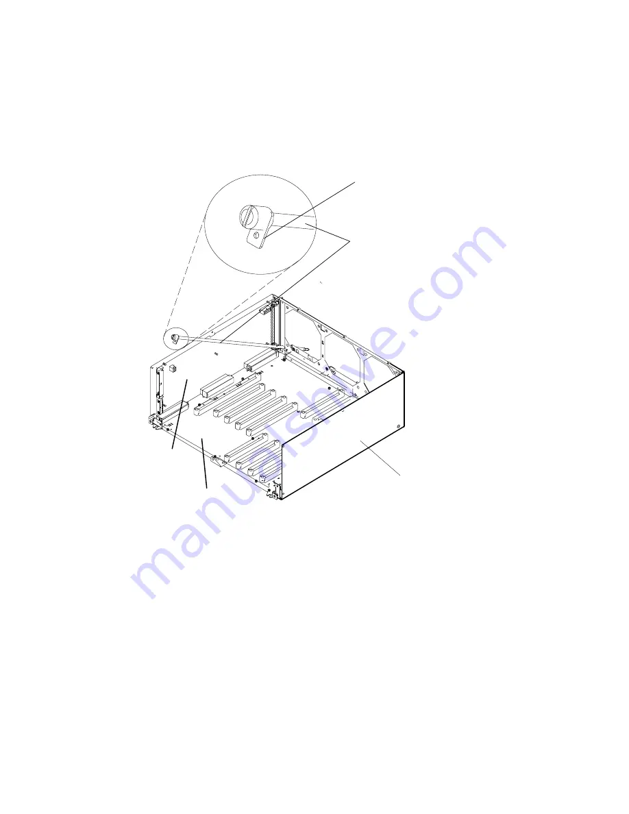
If the CPU enclosure has a docking screw retention bracket, perform the next two
steps.
4. Remove the screw holding the docking screw retention bracket.
5. Move the docking screw aside to provide access to the system planar mounting screws.
Go to step 7.
Lateral
Planar 1
Card
CPU
Module
Docking
Screw
Docking Screw
Retention Bracket
System
Planar
Содержание 7015-R30
Страница 1: ...7015 Models R30 R40 and R50 CPU Enclosure Installation and Service Guide...
Страница 10: ...x Service Guide...
Страница 14: ...xiv Service Guide...
Страница 34: ...1 20 Service Guide...
Страница 206: ...6 2 Service Guide Detail 1 Front Bezel Front Access Plate and CPU Enclosure 1 2 3 4 5 10 11 12 6 10 11 12 9 7 8...
Страница 210: ...6 6 Service Guide Detail 3 Media Module 1 21 22 2 3 7 6 5 4 13 9 8 20 16 14 10 15 17 11 18 23 24 19 12...
Страница 212: ...6 8 Service Guide Detail 4 CPU Module 1 of 3 17 18 19 3 12 1 2 5 6 4 7 20 21 22 14 8 9 10 16 15 24 25 11 13 23...
Страница 214: ...6 10 Service Guide Detail 5 CPU Module 2 of 3 26 27 29 30 31 32 33 34 28 35...
Страница 216: ...6 12 Service Guide Detail 6 CPU Module 3 of 3 36 37...
Страница 252: ...B 8 Installation and Service Guide...
Страница 288: ...Service Guide D 30...
Страница 299: ......
Страница 300: ...Printed in the U S A SA23 2743 02 40H7126...


