4-38
Service Guide
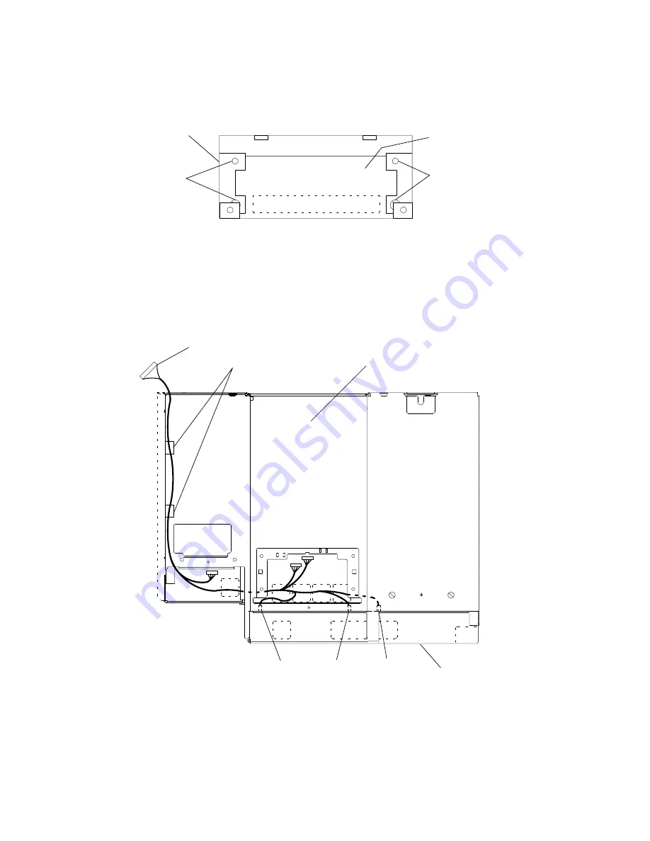
23.If you are removing the docking connector card and cable from the operator panel
docking bracket, remove the four mounting screws, and then remove the card and cable.
Docking
Connector
Card
Mounting
Screws
Docking
Bracket
Mounting
Screws
24.If you are removing the power cable assembly, perform the following substeps:
a. Using pliers, gently remove connectors P71, P72, and P73 from the rear of the media
module.
b. Remove the power cable from the plastic cable retainers, and then guide the power
cable out of the media module.
Bottom View of Media Module
Bottom of Media Module
Rear of
Media Module
P72
(Fan 5)
P71
(Fan 7)
Cable Retainers
P7
P73
(Fan 6)
Note: If connector P71 on your cable is marked “Fan 4,” disregard. This connector
connects Fan 7, as shown in the figure above.
Replacement
Replace in the reverse order.
Содержание 7015-R30
Страница 1: ...7015 Models R30 R40 and R50 CPU Enclosure Installation and Service Guide...
Страница 10: ...x Service Guide...
Страница 14: ...xiv Service Guide...
Страница 34: ...1 20 Service Guide...
Страница 206: ...6 2 Service Guide Detail 1 Front Bezel Front Access Plate and CPU Enclosure 1 2 3 4 5 10 11 12 6 10 11 12 9 7 8...
Страница 210: ...6 6 Service Guide Detail 3 Media Module 1 21 22 2 3 7 6 5 4 13 9 8 20 16 14 10 15 17 11 18 23 24 19 12...
Страница 212: ...6 8 Service Guide Detail 4 CPU Module 1 of 3 17 18 19 3 12 1 2 5 6 4 7 20 21 22 14 8 9 10 16 15 24 25 11 13 23...
Страница 214: ...6 10 Service Guide Detail 5 CPU Module 2 of 3 26 27 29 30 31 32 33 34 28 35...
Страница 216: ...6 12 Service Guide Detail 6 CPU Module 3 of 3 36 37...
Страница 252: ...B 8 Installation and Service Guide...
Страница 288: ...Service Guide D 30...
Страница 299: ......
Страница 300: ...Printed in the U S A SA23 2743 02 40H7126...


