Removal and Replacement
4-49
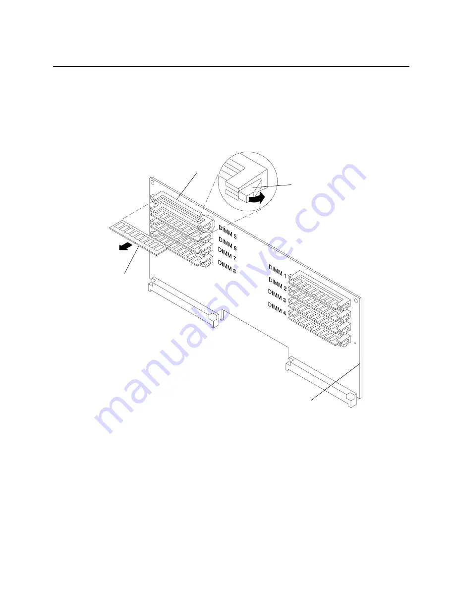
Memory Modules
Removal
1. Remove the memory card from the CPU module, refer to the “Memory Card, CPU Card,
or I/O Card” removal procedure on page 4-45.
2. Push the release tabs away from the memory module until the memory module
disengages from the slot, and then remove the memory module.
Release Tab
Front of Memory Card
Slot
memory
module
Replacement
1. Place the memory module in the slot on the memory card, and then press the memory
module into the slot until the memory module is firmly seated.
2. Replace the memory card. Refer to the “Memory Card, CPU Card, or I/O Card”
procedure on page 4-45.
For information about memory type, memory module size, and memory module part
numbers, refer to Appendix C in the
Diagnostic Information For Micro Channel Bus
Systems.
Содержание 7015-R30
Страница 1: ...7015 Models R30 R40 and R50 CPU Enclosure Installation and Service Guide...
Страница 10: ...x Service Guide...
Страница 14: ...xiv Service Guide...
Страница 34: ...1 20 Service Guide...
Страница 206: ...6 2 Service Guide Detail 1 Front Bezel Front Access Plate and CPU Enclosure 1 2 3 4 5 10 11 12 6 10 11 12 9 7 8...
Страница 210: ...6 6 Service Guide Detail 3 Media Module 1 21 22 2 3 7 6 5 4 13 9 8 20 16 14 10 15 17 11 18 23 24 19 12...
Страница 212: ...6 8 Service Guide Detail 4 CPU Module 1 of 3 17 18 19 3 12 1 2 5 6 4 7 20 21 22 14 8 9 10 16 15 24 25 11 13 23...
Страница 214: ...6 10 Service Guide Detail 5 CPU Module 2 of 3 26 27 29 30 31 32 33 34 28 35...
Страница 216: ...6 12 Service Guide Detail 6 CPU Module 3 of 3 36 37...
Страница 252: ...B 8 Installation and Service Guide...
Страница 288: ...Service Guide D 30...
Страница 299: ......
Страница 300: ...Printed in the U S A SA23 2743 02 40H7126...


