4-40
Service Guide
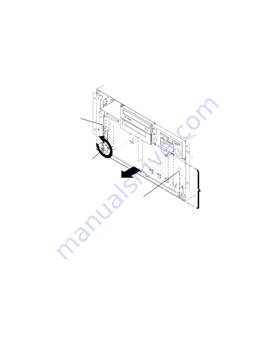
3. Remove the two retainer screws.
4. Loosen the docking screw until the CPU module is disengaged from the I/O planar
interface connectors.
5. Grasp the front of the CPU module, and then pull the CPU module toward you until you
can grasp the bottom of the CPU module on each side.
Front View of CPU Enclosure
Retainer Screw
Docking Screw
Retainer
Screw
CPU
Module
Содержание 7015-R30
Страница 1: ...7015 Models R30 R40 and R50 CPU Enclosure Installation and Service Guide...
Страница 10: ...x Service Guide...
Страница 14: ...xiv Service Guide...
Страница 34: ...1 20 Service Guide...
Страница 206: ...6 2 Service Guide Detail 1 Front Bezel Front Access Plate and CPU Enclosure 1 2 3 4 5 10 11 12 6 10 11 12 9 7 8...
Страница 210: ...6 6 Service Guide Detail 3 Media Module 1 21 22 2 3 7 6 5 4 13 9 8 20 16 14 10 15 17 11 18 23 24 19 12...
Страница 212: ...6 8 Service Guide Detail 4 CPU Module 1 of 3 17 18 19 3 12 1 2 5 6 4 7 20 21 22 14 8 9 10 16 15 24 25 11 13 23...
Страница 214: ...6 10 Service Guide Detail 5 CPU Module 2 of 3 26 27 29 30 31 32 33 34 28 35...
Страница 216: ...6 12 Service Guide Detail 6 CPU Module 3 of 3 36 37...
Страница 252: ...B 8 Installation and Service Guide...
Страница 288: ...Service Guide D 30...
Страница 299: ......
Страница 300: ...Printed in the U S A SA23 2743 02 40H7126...


