background image

G1E Programming Manual 


83


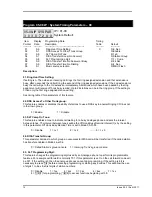
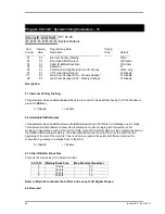
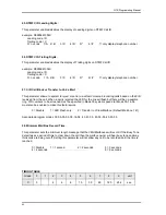
05: DISA Special Function Access: 

 
This parameter sets which of the system functions are able to be accessed by DISA callers. 
 

0 =  DISA can access an outside line by  [9]/[0] + Password. 

                    User can access mail box from external call by [#] 
     

1 = DISA cannot access an outside line by  [9]/[0] + Password. 

                   User can access mail box from external call by [#] 
              2 = DISA can access an outside line by  [9]/[0] + Password. 
                    User cannot access mail box from external call by [#] 
     

3 = DISA cannot access an outside line by  [9]/[0] + Password 

                   User cannot access mail box from external call by [#] 
 

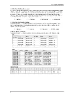
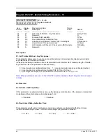
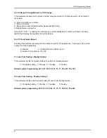
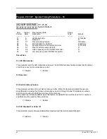
06. DISA Re-check Times To Station/Console: 

 
This function sets the number of times that an unsuccessful DISA call will attempt to retry a station and 
or transfer to a console after the ringing time set in Mode 05-08-06 depending on the setting for 
individual stations in Mode 46-st-04. If polarity reversal or Clear Forward is available and enabled, set 
this parameter to 9 and the call will continue to retry until the caller hangs up. 


0 = 2 times   

1 = 3 times   

2 = 4 times  ..........8= 10 times   

9 = Infinite times 

07. Door Phone Ringing Time: 

 
This parameter sets the time that Door Phone ring assigned stations will ring for when the Door Phone 
button is pressed. 


0 = 5 Sec.   

1 = 10 Sec.   

2 = 15 Sec.   

3 = 20 Sec  ...........9 = 50 Sec. 

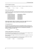
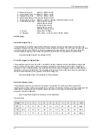
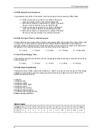
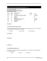
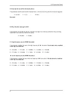
08. DISA Single Digit Dialling: 


This feature allows a DISA caller to dial stations by 1 digit (1-8) using the Hunt Groups (01-08) settings 
in Mode 67, 68, and 69 to set which station(s) will be dialled by each digit. See mode 05-16-03 for 
additional setting information. 
 
 
0=Disable 
1=Enable at Day 
2=Enable at Night 
3=Enable at Day & Night 
4=Enable at Noon 
5=Enable at Noon & Day 
6=Enable at Noon & Night 
7=Enable at Noon & Night & Day 

Please reference 05-16-03 


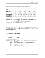
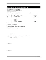
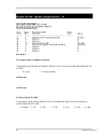
TIMING TABLE 


Grade 

unit 

15 

30 

60 

120 

254 

sec. 


Содержание G1E

Страница 1: ...The Business Telephone Specialists G1E G1E Hybrid IP Telephone System ISDN Digital Telephone System Installation Programming Manual V 3 3 2 ...

Страница 2: ...akes no warranty or representation either express or implied with respect to merchantability or fitness of its products for a particular purpose 2006 2011 Auto Telecom Company Ltd This document or any parts thereof are not to be reproduced or transmitted in any form or by any means electronic or mechanical including photocopying recording or information storage and retrieval systems for any purpos...

Страница 3: ...ent and shall be easily accessible 9 This product is equipped with a three wire grounding type plug this plug will only fit into a grounding type power outlet This is a safety feature If you are unable to insert the plug into the outlet contact your electrician to replace your obsolete outlet Do not defeat the safety purpose of the grounding type plug 10 Do not allow anything to rest on the power ...

Страница 4: ...DN INSTALLATION 2 ECONOMY AND EFFICIENCY 3 EASY INSTALLATION 5 EASY MAINTENANCE 5 FLEXIBILITY OF SYSTEM APPLICATIONS 5 VARIED EXTENSION ALTERNATIVES 5 FULL ISDN AND VOIP FEATURES 6 LIQUID CRYSTAL DISPLAY 6 MECHANICAL SPECIFICATIONS KEY SERVICE UNIT 8 MECHANICAL SPECIFICATIONS BATTERY BACK UP HOUSING 8 ENVIRONMENTAL SPECIFICATIONS 8 POWER CONSUMPTION 8 FEATURES 9 SYSTEM FEATURES 9 STATION FEATURES ...

Страница 5: ...1E STU 8 PORT DIGITAL STATION CARD 26 G1E SLU 8 PORT SINGLE LINE STATION CARD 26 G1 RGU RING GENERATOR UNIT 27 G1E MSC MULTI SERVICE CARD G1E ONLY 27 G1E RPC REMOTE PROGRAMMING CARD G1E ONLY 27 G1E VMC 4PORT VOICE MAIL CARD 28 G1E VMU2 1GIG 4 CHANNELS 29 HOURS MESSAGE STORAGE FUTURE 28 G1E AMS FUTURE 29 INSTALL G1E STU 8 PORT DIGITAL STATION CARD 30 INSTALL G1E SLU 8PORT SINGLE LINE STATION CARD 3...

Страница 6: ...HOLD CONNECTIONS 49 RS232 PORT CONNECTION 50 VMU SETUP 51 INTERNAL MUSIC ON HOLD SOURCE 51 EXTERNAL MUSIC ON HOLD SOURCE G1E 51 POWER ON AND OPERATIONAL TEST 52 OPERATIONAL TESTS 52 SPECIAL IMMUNITY PROTECTION FOR SYSTEM AND TERMINALS 52 PROGRAMMING INFORMATION 54 New Systems 54 PROGRAM 01 TK IP DAY RINGING AND RINGING LINE PREFERENCE ASSIGNMENT 60 PROGRAM 02 TK IP NIGHT RINGING AND RINGING LINE P...

Страница 7: ...HOOKFLASH ANSWER DELAY 69 06 SPEED DIALLING DISTRIBUTION 69 07 SINGLE DIGIT INTERCOM 69 08 MESSAGE WAITING METHOD FOR ANALOGUE PHONES 69 PROGRAM 05 05 IP SYSTEM TIMING PARAMETERS 05 70 01 MORNING CALL 70 02 METERING DETECTOR 70 03 04 SPEED DIAL UNRESTRICTED 1 2 70 05 NAME FUNCTION 71 06 RESERVED 71 07 AUTO REDIAL TIMES 71 08 AUTO REDIAL PAUSE TIME 71 PROGRAM 05 06 IP SYSTEM TIMING PARAMETERS 06 72...

Страница 8: ...BACK TONE 82 04 DISA ECF ACCESS DELAY TIME NIGHT 82 05 DISA SPECIAL FUNCTION ACCESS 83 06 DISA RE CHECK TIMES TO STATION CONSOLE 83 07 DOOR PHONE RINGING TIME 83 08 DISA SINGLE DIGIT DIALLING 83 PROGRAM 05 12 IP SYSTEM TIMING PARAMETERS 12 84 01 CALL TRANSFER METHOD KEY TELEPHONE 84 02 RESERVED 84 03 EXCLUSIVE HOLD CAPABILITY 84 04 DOOR UNLOCK RELAY ACTIVATION TIME 84 05 VOICE MAIL CALL FORWARD PR...

Страница 9: ...ENSION NUMBER 94 04 DISA ECF ACCESS DELAY TIME LUNCH MODE 94 05 DTMF CID LEADING DIGITS 95 06 DTMF CID TRAILING DIGITS 95 07 CID CALL BLOCK OR TRANSFER TO VOICE MAIL 95 08 MINIMUM MAIL BOX RECORD TIME 95 PROGRAM 05 18 IP SYSTEM TIMING PARAMETERS 18 96 01 LED MAINTENANCE 96 02 RESERVED 96 03 DIAL OUT HISTORY FEATURE 96 04 FSK STANDARD FOR CALLER ID 96 05 SECURITY ALARM AND FIRE ALARM STOP TIMER 97 ...

Страница 10: ...RVED 105 PROGRAM 05 23 IP SYSTEM TIMING PARAMETERS 23 106 01 RESERVED 106 02 RESERVED 106 03 RESERVED 106 04 RESERVED 106 05 RESERVED 106 06 RESERVED 106 07 DSP WATCHDOG RESET 107 08 REMOTE AND LOCAL PROGRAM UPDATE VERIFICATION 107 PROGRAM 05 24 IP SYSTEM TIMING PARAMETERS 24 108 01 RESERVED 108 02 RESERVED 108 03 RESERVED 108 04 G1E MONITOR SYSTEM TRACKING 108 05 RESERVED 108 06 G1E MONITOR OUTPU...

Страница 11: ...8 03 TRUNK TRANSMIT GAIN 128 04 SET RING FREQUENCY DK HANDSETS 129 05 ALLOW AUDIBLE RING FOR INCOMING CALLS 129 06 POLARITY REVERSE DETECTION INDIVIDUAL TRUNK OUTGOING 129 07 CO DELAYED RING TIMER TO HUNTING GROUP 129 08 CO DELAYED RING OVERFLOW HUNTING GROUP 129 PROGRAM 35 TK IP TRUNK SPECIFICATIONS 1 130 01 TRUNK TYPE 130 02 TRUNK SIGNAL 130 03 EXTERNAL CALL FORWARD ECF 130 04 DISA ECF DIRECT IN...

Страница 12: ...ION CLASS OF SERVICE 2 146 01 SYSTEM ALARM 146 02 HOLD FEATURE 146 03 CALL SPLIT 146 04 MANUAL LINE 147 05 HEADSET FEATURE 147 06 USE ENGINEERING PASSWORD 147 07 DTMF RECEIVER CONTROL FOR VOICE MAIL PORTS 147 08 STATION ALARM SIGNAL 147 PROGRAM 45 STN IP STATION CLASS OF SERVICE 3 148 01 INTERCOM CALL LIMITATION 148 02 ACP HEAR BGM AT IDLE STATE 148 03 RING INCREASE 148 04 ALLOW TRUNK ACCESS 148 0...

Страница 13: ...GROUP PILOT NUMBER 161 01 HUNTING GROUP PILOT NUMBER 161 02 HUNTING GROUP RINGING METHOD 161 PROGRAM 68 GP IP HUNT GROUP ASSIGNMENT DAY 162 PROGRAM 69 GP IP HUNT GROUP ASSIGNMENT NIGHT LUNCHTIME 163 PROGRAM 70 CD IP ISDN INTERFACE SPECIFICATIONS PROGRAM G1E 164 PROGRAM 71 CD IP CALLING LINE IDENTIFICATION PRESENTATION 165 PROGRAM 72 ST ISDN CALLED PARTY EXTENSION NUMBER ASSIGNMENT 166 PROGRAM 73 S...

Страница 14: ... NUMBER CHARGING 179 PROGRAM 94 TK IP LUNCHTIME RINGING AND RINGING LINE PREFERENCE ASSIGNMENT 181 PROGRAM 95 TK IP TRUNK SPECIFICATIONS 3 182 01 DETECT FAX SIGNAL 182 02 RESERVED 182 03 TRUNK CALL DURATION 182 04 DISA AND ECF LUNCH TIME SETTING 182 05 RESERVED 183 06 DUET DISTINCTIVE RINGING SETTING 183 07 RESERVED 183 08 RESERVED 183 PROGRAMMING CROSS REFERENCE 184 INCOMING CALLS 184 OUTGOING CA...

Страница 15: ...TION 188 PROGRAMMING OPERATIONS 189 ACD 1 OPERATION 189 DISA AND AUTO ATTENDANT OPERATION 191 INSTALLING ACP S 194 SETTING UP DUET RING DETECT 195 PC UPGRADE PROCESS FOR G1E G1E SOFTWARE 197 Hardware requirements 197 Software requirements 197 ...

Страница 16: ...Issue 3 3 2 April 2011 ...

Страница 17: ...the cabinet to be a master to between 1 and 4 cabinets and the operating system to be converted to the GDS software with all GDS feature sets available Expansion Cabinets Expansion cabinets for the G1E system are a standard G1E main equipment with the MXU4 card fitted allowing the cabinet to connect to the MPU4 of the master cabinet Each additional cabinet adds the full extra capacity of the cabin...

Страница 18: ... instructions may cause interference to radio and television reception It has been type tested and found to comply with the limits for a Class A computing device in accordance with the specification in Subpart J of Part 15 of FCC Rules which are designed to provide reasonable protection against such interference in a residential installation However this is no guarantee that interference will not ...

Страница 19: ...nd other office home equipment Key highlights of the G1E series include Economy and Efficiency The base system is equipped to support four 4 CO lines or three ISDN BRI s eight 8 digital stations and 4 analogue stations The system may be expanded to a maximum of eight 8 CO lines six 6 ISDN BRI s or 6 VOIP connections Station cards may be selected to allow practically any combination ranging from al...

Страница 20: ...s well as residential applications At the forefront of the system design is a universal concept to adapting and connecting with a variety of communications devices Productive HYBREX Digital Key Telephones offer thoughtfully designed productive feature access to keep you connected with one another and customers Auto Telecom technology leads the industry in providing for compatibility with devices s...

Страница 21: ...l can easily communicate and perform programming right over the telephone HYBREX telephone systems allow programming and voice conversations to be performed at the same time Advanced software upgrades Through the RS232 connection system software can be upgraded easily without replacing any firmware Flexibility of System Applications Unlike other conventional systems in the G1E size range the insta...

Страница 22: ...d LCD display The LCD is 32 64 for DK2 21 characters total comprised of 2 rows by 16 characters 4 rows of 16 each This LCD provides an invaluable tool for simplifying the use of the telephone by identifying the calling extension by name outside lines by name and self prompting displays for feature access Station feature usage is made simple with the help of the LCD display Continuous prompting inf...

Страница 23: ...G1E General Description 7 DK1 21 DK1 31 Obsolete ACP and DOORPHONES DK2 21 DK2 21 with DSS Console DK3 21 DK3 33 ...

Страница 24: ... Sensor Twisted 1 Pair 2 wires Single Line Telephone Twisted 1 Pair 2 wires Mechanical Specifications Key Service Unit CABINET DIMENSIONS 425mm W 85mm D 315mm H 16 7 3 3 12 4 WEIGHT 3 9 Kg Configuration 4 x 8 8 59 lbs Mechanical Specifications Battery Back Up Housing CABINET DIMENSIONS 36 cm W 13 cm D 44 cm H WEIGHT With Batteries 16 lbs 7 25Kgs Without Batteries 4 lbs 1 8Kgs Mounting Screws 12 25...

Страница 25: ...an 2 3 or 4 Digit Flexible Time Format 12 24 Hour Forced Account Code Assignment Intercom Intercom Single Digit Assignment Intercom Ring Voice Select Intercom Dialling Restriction ISDN Call Charge Metering Information Caller Identification Direct Inward Dialling Call Forward Internal External Call Waiting MSN Multiple Subscriber Number Sub addressing User to User Signalling Host PABX Access Hot li...

Страница 26: ......

Страница 27: ... Display LCD Phones Calling Number Display LCD Phones Camp On Chain Dialling Conference Dial By Name LCD Phones Dial Access to Attendant Direct Station Selection Doorphone Access Do Not Disturb DND Dual Color LED Duration Time Display LCD Phones Executive Override Barge In External Call Forwarding Flash Open Loop Timed Flash Hands free Answer Back Hearing Aid Compatibility Headset Compatibility Ho...

Страница 28: ... keys and 7 function keys for feature access DSS CO Lines and speed dial DK1 21 Obsolete Multifunction Key Telephone Includes 32 character LCD display speakerphone Handsfree headset jack 20 dual colour keys and 14 function keys for feature access DSS CO Lines and speed DK2 21 Multifunction Key Telephone with 4 line 64 character LCD display speakerphone and handsfree 22 dual colour keys and 14 func...

Страница 29: ...PCM 4 HDLC 3 PCM 3 HDLC 2 PCM 2 Cabinet 2 Cabinet 3 Key Service Unit which includes Power Supply Unit G1E PWU G1 RGU Main Board Unit G1E MBU Common Control eight digital port circuits and 4 SLT ports on board messaging and Auto Attendant Multi cabinet system includes MPU4 and MXU4 Trunk Unit G1E TKU G1E SIU G1E VIU Optional Expansion Cards Trunk Card G1E TKU G1E SIU G1E VIU G1E ITU Digital Station...

Страница 30: ...14 Issue 3 3 2 April 2011 G1E Main Equipment with MSC VMC 2 TKU s 2 STU s Installed ...

Страница 31: ...G1E Programming Manual 15 G1E Main Equipment ...

Страница 32: ... be easily accessible Input power Line capacity requirements 10 amperes CAUTION DOUBLE POLE NEUTRAL FUSING ON EUROPEAN PLUGS SURGE PROTECTION A Surge Protector is recommended on the dedicated AC line VENTILATION AND TEMPERATURE Humidity 10 to 95 relative non condensing Temperature 32 to 113 0 to 45 EARTH GROUND A proper ground connection 14 AWG SERVICEABILITY Lighting conditions and working space ...

Страница 33: ...nstalling printed circuit cards on to header pins of the main board in the basic cabinet Take your time and extra care to assure the printed circuit cards are properly aligned After installing each option and expansion card perform a visual inspection to assure the printed circuit card is installed properly 1 Position the cabinet on a flat surface like a table or countertop Avoid doing this on car...

Страница 34: ...y Interface Card 1 CN3 AC IN 2 CN6 CN8 AC110V 90 130VAC 3 CN6 CN7 AC220 180 260VAC 4 CN10 Battery Connection 24V to 27V DC 5 LED2 LED2 6 LED1 G1E PWU DC 32V indication 7 CN2 Cable connection from G1E PWU to G1 RGU CN1 8 CN1 Cable connection from G1E PWU to G1E MBU ...

Страница 35: ...bin 1 to Cabin 2 10 RS232 RS232 Port 11 PCM4 Expansion PCM Data transfer from Cabin 1 to Cabin 4 12 PCM3 Expansion PCM Data transfer from Cabin 1 to Cabin 3 13 PCM2 Expansion PCM Data transfer from Cabin 1 to Cabin 2 14 LAN LAN Port 15 SW2 Reset Switch 16 CN2 CF card 17 SW1 Cabinet switch to select Cabin Not present in later versions The MPU4 is installed in Cabinet 1 only Once installed the softw...

Страница 36: ...3 PCM Data connection from G1E MPU4 to G1E MXU 4 SW1 Cabinet switch to select Cabin 2 4 The MXU4 is installed in Cabinet 2 4 only Once installed the software in the MBU s must be changed to a GDS G1E version and then the G1E programming method will be replaced by GDS programming method using a Web browser via the network connection in Cabinet 1 1 2 4 3 ...

Страница 37: ...on indication when LED1 slow flashing is normal 7 JP1 Clear Flash Memory Normal Operation 8 CN6 To G1E VMC CN1 9 CN4 To G1E MPU4 CN1 G1E MXU CN1 10 CN3 G1E STU G1E SLU CN1 11 CN8 SLT Ports 41 42 12 CN11 SLT Ports 43 44 13 CN10 Digital Ports 11 18 14 CN5 RS232 connection to PC for SM5 Winloader SMDR etc 15 CN3 Relay Sensor External page 16 CN14 External Music 17 LED3 DSP LED 1 5 6 4 3 2 8 9 13 7 11...

Страница 38: ...P 5 SW1 Reset Switch 6 LED1 Power LED 7 JP1 Clear Flash Memory Normal Operation NOTE PLEASE READ MBU MARKINGS CAREFULLY THERE ARE 2 DIFFERENT MBU LAYOUTS IN G1E MBU S WITH DIFFERENT ORIENTATIONS OF JUMPERS 8 CN4 To G1E MSC CN1 9 CN6 To G1E VMC CN1 10 CN3 G1E STU G1E SLU CN1 11 CN8 SLT Ports 41 42 12 CN11 SLT Ports 43 44 13 CN10 Digital Ports 11 18 ...

Страница 39: ...o 4 input from Central Office 4 K15 Ground 5 JP1 TKU1 TKU2 switch to select TKU1 CO1 CO4 or TKU2 CO5 CO8 G1E SIU 3 BRA ISDN Card 1 CN1 BRA 1 to 3 input from Central Office 2 CN2A C ISDN Terminator switches 3 CN4 To G1E MBU CN7 4 JP1 SIU1 SIU2 switch to select SIU1 CO1 CO6 or SIU2 CO7 12 5 LED 1A 1B 1C For Bra connection indication ...

Страница 40: ...to SIP Proxy Server successfully Green slow flash means it has not registered to SIP Proxy 2 LED2 Green steady on means system power is applied 3 SW1 Reset Switch 4 J4 RS232 port 5 J1 LAN Port 6 J2 PC Port 7 CN2 To G1E MBU CN7 8 CN1 To G1E MBU CN2 9 JP1 VIU1 VIU2 switch to select VIU1 CO1 CO3 or VIU2 CO5 CO7 ...

Страница 41: ...stem will still see as TK2 but trunks will start from 801 If ITU card only is installed up to 12 VOIP trunks are available depending on ITC card installed When the configuration is TKU plus ITU4 the total number of trunks will be 4 PSTN and 4 VOIP and when an ITC4 is installed on the ITU the total number of trunks will be 4 PSTN and 8 VOIP When the configuration is SIU card plus ITU4 the total num...

Страница 42: ...1 38 3 CN2 Connection for 8 Digital stations G1E SLU 8 Port Single Line Station Card 1 CN1 Connection to G1E MBU CN3 2 CN2 Connections for ST1 ST8 3 CN3 Power fail connection to G1E TKU CN2 CO1 4 or CO5 8 to ST1 ST4 4 JP1 Switch to select SLU1 ports 21 28 or SLU2 ports 31 38 Note G1E SLU requires the installation of the G1 RGU for correct operation ...

Страница 43: ...Generator Unit 1 CN1 DC 32V DC 70V to G1E PWU CN2 G1E MSC Multi Service Card G1E Only 1 CN1 Connection to G1E MBU CN4 2 CN2 RS232 RS232 connection to PC for SM5 Winloader SMDR etc 3 CN3 Relay Sensor G1E RPC Remote Programming Card G1E Only ...

Страница 44: ...Unit Duration Duration Unit Duration mins hours Unit Duration mins hours 128Mb 1000 30 Secs 500 8 1000 60 Secs 1000 16 G1E VMU2 1Gig 4 Channels 29 Hours Message Storage Future For a description of the VMU and Auto Attendant setup and configuration including how to record messages see the section at the end of the Installation Manual ...

Страница 45: ...itch 6 LED 1 4 LED 1 LAN Port Connection status indicator LED 2 WAN Port Connection status indicator LED 3 Heart beat of IPP Flashing means work normally LED 4 Communication Status between VSU and CPU on board 7 Expansion terminal for ITC card 8 UART RS232 Programming Communication interface Port 1 6 3 4 5 7 8 2 ...

Страница 46: ...he MBU and then fasten STU to spacers using the 4 screws removed from the MBU Installing the second Expansion card Power off the system Set the Jumper on the card to STU2 Install 4 brass spacers to the first STU by removing screws from the STU and replacing with spacers Plug the cable from the MBU to the first STU to the second STU and then fasten STU to spacers using the 4 screws removed from the...

Страница 47: ...g the second Expansion card Power off the system Set the Jumper on the card to SLU2 Install 4 brass spacers to the first SLU by removing screws from the SLU and replacing with spacers Plug the cable from the MBU to the first SLU to the second SLU and fasten SLU to spacers using the 4 screws removed from the first SLU Make certain that the cable is pushed home firmly into the connector Power fail P...

Страница 48: ...nect the G1 RGU CN1 to the G1E PWU CN2 using the supplied cable Note The G1 RGU must be installed before installing any G1E SLU cards Current G1E Stock has RGU as standard Make certain that the cable is pushed home firmly into the connector Install G1E RPC Remote Programming Card To G1E MBU2 The RPC card will only be able to be fitted to second generation G1E MBU s ...

Страница 49: ...d Power off the system Set the Jumper on the card to TKU2 Install the 4 brass spacers to the first TKU by removing the screws from the TKU and fitting spacers Plug the cable from the MBU to the first TKU to the second TKU and then fasten TKU to spacers using the 4 screws removed from the first TKU The cable from TKU card CN2 can be connected to CN3 of the G1E SLU for power fail operation Make cert...

Страница 50: ...nto the MBU Installing the second ISDN Trunk card Power off the system Set the Jumper on the card to SIU2 position Install the 4 brass spacers to the first SIU by removing the screws from the SIU and fitting spacers Plug the cable from the MBU to the first SIU to the second SIU and then fasten SIU to spacers using the 4 screws removed from the first SIU Make certain that the cable is pushed home f...

Страница 51: ...10 ITU switch to select ITU1 or ITU2 Must be set ITU2 position Installing the IP Trunk card The first card must be a G1E TKU or G1E SIU card The ITU will always be the second card Power off the system Set the Jumper on the card to ITU2 position if fitted Install the 4 brass spacers to the first TKU SIU by removing the screws from the ITU and fitting spacers Plug the cable from the MBU to the first...

Страница 52: ... system Set the Jumper on the card to VIU2 Install the 4 brass spacers to the first VIU by removing the screws from the VIU and fitting spacers Plug the cables from the MBU to the first VIU to the second VIU and then fasten VIU to spacers using the 4 screws removed from the first VIU Make certain that the cable is pushed home firmly into the connector To Install G1E VIU in G1E it will be necessary...

Страница 53: ...cer Long spacer for G1E short spacer for G1E Mount G1E VMC CN1 to G1E G1E MBU CN6 Screw VMC to Brass spacer Make certain that the card is aligned correctly and pushed home firmly into the connector For a description of the VMU and Auto Attendant setup and configuration including how to record messages see the section at the end of the Installation Manual ...

Страница 54: ...r direct connection to a PC If the IPP is already installed on the customer network then it is better to use the customers PC for programming or connect your laptop to the customers network Step 2 Default value of IPP IP Address 10 10 10 6 User name ADMIN Upper case Password 1234 Note 1 If IPP has not been installed you can use a cross LAN cable to access it by the default IP Address 2 If IPP is i...

Страница 55: ...n Jumper Verify that the input voltage and input voltage jumper are correct before you power on the system The input voltage is set according to the Customer s requirement before shipping However it is important to verify that the setting is correct prior to initial system power up Power Supply voltage options for the unit 100 VAC 100 to 120 V AC 50 60Hz or 240 VAC 205 to 265 V AC 50 60Hz Preparin...

Страница 56: ...sive and may cause damage to the eyes or skin It may be toxic if swallowed 4 Exercise care in handling batteries in order not to short the battery with conducting materials such as rings bracelets and keys The battery or conductor may overheat and cause burns This product is defined as a secondary battery operated device As such the following instructions should also be read and followed 1 Charge ...

Страница 57: ...onnector Attention to proper cabling will go a long way towards a successful installation and minimizing service calls after installation Some guidelines for running station cable are as follows z Avoid running cable parallel to fluorescent light fixtures or electrical lines not in conduit If these obstacles are unavoidable run the cable at right angles across them z Do not run station cable insid...

Страница 58: ...minal with GRN terminal screws of the modular jack Ring with RED z There is no polarity requirement on Tip and Ring z 2 conductor wiring is required for DK series Digital Key Telephones z For DK 1 phones open the overlay of the function key on DK1 telephone and select the 1st station position ALL phones are to be set to this position for the G1E z For DK 1DK2 and DK3 phones the switch is located t...

Страница 59: ...e on connector locations 11 38 z Connect Tip Ring terminals from KSU G1E MBU G1E STU to the ACP connector 6 contacts z There is no polarity requirement on Tip and Ring z Connect Relay for applications such as door open to the ACP connector 6 contacts z Connect Sensor for applications such as door open alarm to the ACP connector 6 contacts z Mount ACP connector on to ACP itself z Select the 1st sta...

Страница 60: ...inate the station wires with the connectors that are provided The stations will connect to the KSU as shown on the main panel on connector locations 21 28 or 31 38 Needs G1E SLU s installed or 41 44 z Connect Tip terminal with GRN terminal screws of the modular jack Ring with RED z There is no polarity requirement on Tip and Ring z 2 conductor wiring is required for Single Line Telephones ...

Страница 61: ... z Connector PIN assignment Pin 1 2 7 8 are reserved z Install remove the terminators by adjusting the jumper JP1 A B C and JP2 A B C on SIU card If there is no other ISDN device connected after the ISDN interface of SIU card when using point to multi point connection this ISDN interface port needs the terminator installed Otherwise remove the terminator Example The following is the point to multi...

Страница 62: ...pril 2011 If the connection is Point to Point then the terminator must be installed always Unless there is a specific need for Point to Multi Point connection it is strongly recommended that Point to Point ONLY is used ...

Страница 63: ...ace Connection If the user has programmed the ISDN interface of SIU to a T Interface the wiring should be z S Interface Connection If the user has programmed the ISDN interface of SIU to a S Interface the wiring should be as the following ...

Страница 64: ...us d2 100m 200m Length limitation by round trip delay 10us to 14us not by attenuation d3 Recommendation with a cord having a minimum length of 5m and not more than 10m 5m d3 10m Extended Passive Bus d4 500m 800m Length limitation by round trip delay 10us to 14us not by attenuation d5 25m 50m Length limitation between TE s by differential round trip delay of 2us ...

Страница 65: ...Connect the sensor to pins 2 and 5 of the RJ 11 connector z Refer to System Programming Mode 39 Sensor Assignment Paging Output G1E z The Paging output is available on G1E only z The Paging output is available on pins 3 and 4 Refer to Illustration Door Switch Sensor Music on Hold Connection G1E Connect an external music source to an SLT Port via an approved line isolation unit Music on Hold Connec...

Страница 66: ...nect the RJ 11 to the KSU with a 6 conductor line cord Insert the line cord into the connector labelled RS 232 Notice Do not exceed the cable length limitation 15M 50 feet for the RS232 connection Connect old style 2 wire devices such as follows G1E Device TD 4 RD Gnd 2 Gnd DTR 1 links to DSR 5 on G1E end only ...

Страница 67: ...this procedure see mode 25 in the Programming manual To access the MBU Flash Ram to setup or record messages dial 8901 from the Console To access the VMU Flash Ram to setup or record messages dial 8902 from the Console Internal Music on Hold Source The G1E and G1E have a 2 Minute MOH message recorded on the MBU Flash ram This message can be recorded by the customer to allow them to use their own m...

Страница 68: ...ts Check each telephone and CO line to verify that outgoing lines are connected properly Check that intercom calls can be made from extension to extension WARNING DISCONNECT THE POWER SUPPLY FROM THE AC POWER SOURCE BEFORE WIRING OR CHANGING ANY WIRING Connect the Battery Backup AFTER AC power has been connected to the Power Supply Disconnect Battery Backup BEFORE disconnecting AC power from the P...

Страница 69: ...G1E Programming Manual 53 PROGRAMMING INFORMATION ...

Страница 70: ...s will not have a system password 3 Press SAVE 4 LCD display will show PROGRAM MODE __ 01 95 5 Enter 2 5 Press SAVE Display will show 25 Reset Data 0 9 Default 6 Enter 2 7 System Database is now reset LCD will display 8 PROGRAM MODE __ 01 95 8 You may commence database entry at this point or exit system programming by pressing SPK key or by lifting and replacing the handset To Enter System Program...

Страница 71: ...oad modify and download the Customer s data 9 Use System Manager to recall the Customer 10 Switch the conversation back to telephone 11 Answer the recall VMC Software upgrades Local 1 Install a VMC card in A system 2 Key phone operation COPY flash memory data to CF card System Auto Attendant stops 3 LCD display XXXX Ready xxxx 0000 26FF After 11 minutes power off and retrieve the VMC 4 Go to custo...

Страница 72: ...rs a Wild Card don t care into Account Codes or Toll control entries LCD will display d lower case letter d to indicate don t care entry HOLD PAUSE Inserts a Pause when programming a Speed Dial Entry or for Voice Mail Programming LCD will display p lower case p to indicate a Pause entry TRF FL FLASH Enters a FLASH command as part of a Speed Dial Entry LCD will display F upper case F to indicate a ...

Страница 73: ...ple errors are made the system will continue to return you to the illegal entries as others are corrected It is not necessary to re enter existing information on a multi item form You need enter only the information that is to be changed You may move the cursor to the left or right in order to access only the specific entry that you want to change You may press SAVE without regard for the placemen...

Страница 74: ...58 Issue 3 3 2 April 2011 ...

Страница 75: ...G1E Programming Manual 59 PROGRAM MODES ...

Страница 76: ... be assigned to no station the location value is set to 0 5 To clear all entries press REDIAL 6 Lunch ringing is programmed in Mode 94 Program 02 tk IP Night Ringing And Ringing Line Preference Assignment 02 tk IP FLX NIG 111 000 000 000 tk 01 12 IP Item Pointer 01 26 Assigned station number General This program assigns each incoming line to ring the programmed stations The ringing methods can be ...

Страница 77: ...s set in Mode 05 12 04 6 Door phone Ringing frequency is set in Mode 05 03 08 Program 04 gp IP Console Assignment 04 gp IP Console 111 000 000 000 gp Station group 01 08 IP 01 04 Assigned station number 2 to 4 digits General This program permits the selection of the consoles in each station group Consoles are stations that can program System speed dials Record system Voice messages receive hold re...

Страница 78: ...utomatically transfer to the Console 02 Exclusive Hold recall time This parameter sets the time duration from when Exclusive hold is initiated to when the held call starts to recall the station After a pre determined recall time see 05 01 03 Hold Recall Timeout if the station still does not answer the held call will recall to the Console in addition to the holding station 03 Hold Recall Timeout Th...

Страница 79: ...ion for speed dial entry trunk access time and voice mail call forwarding tone delay See timing table Grade D for parameters of this feature 07 DTMF Generation Time This parameter permits the selection of DTMF Generation output time The generation time may need to be lengthened to access some Voice Mail or answering machines See timing table Grade E for parameters of this feature 08 Call Forward N...

Страница 80: ...r is for Single Line Telephones If the interval between digits dialled exceeds the assigned time period a Busy Tone will be given See timing table Grade C for parameters of these features 03 Auto Redial Ringing Time PSTN lines This parameter is the time duration for which the system will redial the telephone number automatically and then hang up during Auto Redial on PSTN lines ISDN lines will han...

Страница 81: ... PRESSED Period B HOOK RELEASED Period B SLT Release Time Hold DURING CONVERSATION HOOK PRESSED Period B HOOK RELEASED Period B SLT Release Time Hang Up 07 Ring On Time This parameter allows the system to identify Ring On Time Interval from the Exchange See timing table Grade G for parameters of this feature This parameter should never be changed without a clear understanding of the operation of t...

Страница 82: ...an available trunk according to the assigned dial 9 trunk group when automatic dialling features are used i e Speed Dial Save Redial Redial etc 0 Allowed 1 Not Allowed 03 Intercom Call Signalling Method This parameter selects the Intercom calling method The user can still override this selection by dialling 3 after initiating an intercom call Individual stations can be set to automatic microphone ...

Страница 83: ...e is a Voice Mail system connected to the system as some Voice mail units have problems with the broken dial tone Item 6 will also provide what is known as Stutter dial tone to extensions when they are left a message useful where phones do not have a message light When this is enabled as well as MW direct to handsets by other methods the phones with messages will receive both Message light and stu...

Страница 84: ...ed to change settings in this mode to upgrade software G1E Monitor must be enabled in mode 05 24 0 1200 1 2400 2 3600 SM5 3 7200 4 9600 5 19200 6 38400 7 57600 8 115200 02 Dial 9 Flag This parameter sets if a station can access an outgoing line by dialling 9 If this parameter is disabled the station can still access an outgoing line by pressing a line key 0 Can not access dial 9 feature 1 Can acce...

Страница 85: ...led When names are enabled default then the maximum number of system speed dials is 500 07 Single Digit Intercom Single digit intercom allows the stations to call up to 5 other stations by dialling one digit only 1 to 5 This feature is for the Hotel Motel Environment Up to eight different groups may be programmed If a group is not programmed with any entries then stations which are in the same num...

Страница 86: ...ia SMDR Up to software version 12q the wake up message is sourced from the VMU card from version12r it is sourced from the MBU card To record the morning message press 8901 password 2 3 3 from the console Each station can be set in Mode 44 st 08 to decide whether to hear Background Music or DND tone To record Morning call dial 8901 Password Default 1234 2 3 3 from the console 02 Metering Detector ...

Страница 87: ... dial Trunk Please refer to the programming mode 43 09 35 Note 3 For setting Directory Dial key Please refer to mode 07 06 Reserved 07 Auto Redial Times This parameter is to set the number of auto redial times which the system will attempt 0 0 times 1 2 times 2 5 times 3 9 times 4 19 times 5 29 times 6 39 times 7 49 times 8 59 times 9 69 times 08 Auto Redial Pause Time This parameter is the time d...

Страница 88: ...Timeout This parameter sets the time duration between transferring a call to a station and automatic transfer back to the transferring party when the called party does not answer See timing table Grade M for parameters of these 2 features 03 ISDN Audio This parameter sets ISDN Audio type It should never be necessary to change this mode as the software defaults will be set for each market 0 a law 1...

Страница 89: ...ill override this setting 0 No Limit 1 1 Min 2 2 Min 3 3 Min 4 9 4 Min 07 Hold Feature for SLT This parameter is to set whether Single Line Telephones use FLASH or Hook switch or FLASH 7 or Hook switch 7 to place a call on Hold 0 Normal Using FLASH or Hook switch to put a call on Hold 1 Alternate Using FLASH 7 or Hook switch 7 to put a call on Hold 08 Station Hunting Group Ring Method This paramet...

Страница 90: ... when busy 2 Enable when no answer 3 Enable when busy or no answer 02 Toll Override Prevention from quick dial To protect toll override control when a Key phone selects a trunk and quickly dials one digit and overriding the toll control If Enabled then after selecting a trunk the first digit dialled will be delayed one pause interval 0 Disable 1 Enable 03 Paging Alert Tone This parameter enables d...

Страница 91: ...estrictions being overridden This parameter will be automatically disabled on any lines which are set to Pulse dial 0 Disable 1 Enable 06 SMDR Digit Mask If setting is 0 then the full length of the telephone number will be output to the SMDR If setting is n then the length of the telephone number will be n digits long n 0 to 9 07 Meter Pulse Detect Delay Time CO release guard time This parameter i...

Страница 92: ...re 02 DSS Access To Other Trunk group This feature enables or disables the ability of stations to use a DSS key to answer Ringing CO lines not in their own group 0 Enable 1 Disable 03 SLT Camp On Tone This feature enables a tone to indicate call waiting for a busy Analogue phone and sets the interval between tones The interval between tones will be the Off Hook Busy Remind Interval t x by the sett...

Страница 93: ...n 0 0 Seconds 1 1 Second 2 2 Seconds 9 9 Seconds 08 Music Source Selection This parameter sets the Music Source for the Internal Background Music and CO Music on Hold G1E Set Data B G M MOH Set Data BGM MOH 0 Inbuilt Storage Inbuilt Storage 5 Inbuilt Storage SLT MOH 1 Inbuilt Storage Inbuilt Storage 6 Inbuilt Storage Internal Tone 2 Inbuilt Storage Inbuilt Storage 7 Inbuilt Storage Internal Tone 3...

Страница 94: ...be free The calling station will hear ring back tone instead of busy tone and the first operator in the group will receive the Busy Remind Signal The first operator to go on hook will receive the call 0 Disable 1 Enable 03 Clear Forward Signal Detection Loop Disconnect This feature enables loop disconnection as a Clear Forward Signal 0 Do not detect this signal 1 The Loop Disconnecting Signal 80 m...

Страница 95: ...for this 07 ACD 1 Segment 2 Recall Time This parameter sets the time an ACD 1 call which has been answered by the Overflow message will stay on hold in the ring queue before the system will play the second part of the ACD 1 message to apologize for the continuing delay The call back time for the second message starts at 5 seconds and increases in 5 second increments The message will be played to t...

Страница 96: ...ires more The last digits of the voice mail box number will still have to be the same as the station numbering for correct recognition The HOLD key can be used to insert a pause in the DTMF tone sending and will display as a p The DND key is no digits sent and is shown as d Example The HYBREX is set to 2 digit numbering but the voice mail requires 4 digits The voice mail also requires a pause betw...

Страница 97: ... to wait to listen to tones to see what is happening with calls Answering Machine Operation When activated this function allows the caller to set call forward to the Voice Mail as usual but then monitor calls to the Voice Mail from his key phone on hook and if they wish can lift the handset and take the call back from the Voice Mail To enable the user presses SPK 7 7 3 1 and to disable presses SPK...

Страница 98: ... of 0 the DISA password will be set in mode 13 02 If the parameter is set to 1 50 passwords are available and they will be the same as the forced account codes numbers 50 99 Forced account codes are set in Mode 17 01 99 0 1 password 1 50 Passwords 03 Select Music on Hold or Ring Back Tone This parameter selects what the incoming caller will hear during Ring Transfer and Hold Recall conditions The ...

Страница 99: ...ng on the setting for individual stations in Mode 46 st 04 If polarity reversal or Clear Forward is available and enabled set this parameter to 9 and the call will continue to retry until the caller hangs up 0 2 times 1 3 times 2 4 times 8 10 times 9 Infinite times 07 Door Phone Ringing Time This parameter sets the time that Door Phone ring assigned stations will ring for when the Door Phone butto...

Страница 100: ...dds the ability to transfer a trunk call to another trunk External Call Transfer using the Transfer key rather than the Unsupervised Conference facility 0 Use Key phone s call transfer method 1 Use single line telephone s call transfer method 2 Use Key phone s call transfer method and TRF for Trunk To Trunk 3 Use single line telephone s call transfer method and TRF for Trunk To Trunk Note When par...

Страница 101: ...ular Trunk Group Access If this parameter is set to 0 then line selection will be the first available trunk in the users dial 9 0 group If the parameter is set to 1 then the lines will be selected in a Circular fashion till all lines have been used and then the selection will start again Do NOT use Circular with PSTN lines unless there is a very good reason as call collision will result 0 Linear 1...

Страница 102: ...t or press the SPK key 0 Disable 1 Enable 02 Immediate SMDR output This parameter when enabled will send the SMDR output to the PC Printer immediately a call is made This allows external software to know who is dialling out or who is ringing into the system at this moment In applications such as the Internet Cafe when the customer dials out the system will send out the SMDR information immediately...

Страница 103: ...Enabling this parameter will output the trunk status report for CTI applications Currently 4 is the correct setting for Ct Star applications 0 Disable 4 Enable Extension Status report 5 Enable Trunk output 50 st 04 07 Least Cost Routing Weekly Holiday 1 This parameter set the first weekly holiday for Least Cost Routing feature 0 No weekly holiday 1 Monday 2 Tuesday 7 Sunday Related system Programm...

Страница 104: ... 06 0 1 CID Delay Ring Time 1 1 Sec 07 0 Reserved 0 08 0 Reserved 0 Description 01 SLT LCR Switch on Delay For PSTN This parameter delays the connection of SLT phones direct to PSTN lines when LCR is in use to prevent the SLT dialling from conflicting with the LCR dialling 0 Disable 1 3 seconds delay 4 6 seconds delay 02 Reserved 03 Reserved 04 Reserved 05 DISA DTMF Detect Delay Time This paramete...

Страница 105: ... DISA transfer to ensure that CID information is available and is transferred with the DISA call to the receiving station If Mode 05 17 07 CID Call Screening is enabled it will not work unless this parameter is enabled 0 Disable 1 1 Sec 2 2 Sec 9 9 Sec 07 Reserved 08 Reserved ...

Страница 106: ...mp Method 0 Disable 02 0 1 3 1K Audio for SLT 0 3 1K 03 0 Reserved 0 04 0 Reserved 0 05 1 Reserved 2 06 1 Reserved 0 07 0 Reserved 0 08 0 CLI CFW LED Indication 0 Solid Description 01 VMU Date Stamp Method This parameter selects date time stamp for the VMU card English way 0 Chinese way 1 02 3 1K Audio for SLT This parameter sets analogue phone ports for either audio 3 1k or speech 0 3 1k 1 speech...

Страница 107: ... 05 Reserved 06 Reserved 07 Reserved 08 CLI CFW LED Indication This parameter controls the LED Indication of CLI Status and Call Forward Indication on DK6 and DK7 phones 0 LED flashes DK6 green DK7 red 1 LED Solid Red 2 LED Off ...

Страница 108: ...tandard greeting after DISA answers the incoming call Users can dial either the extension number or the single digit service 1 Two levels When incoming call rings in to the system the external party will hear the Company Greeting to announce Press 1 to access different department by single digit service 2 Two levels When incoming call rings in to the system the external party will hear the Company...

Страница 109: ...format of ACP data output The output can be in plain text or CTI output format 0 CTI format output to RS232 and ACP data output ON 1 Text format output to RS232 and ACP data output OFF 2 CTI format output to RS232 and ACP data output ON 3 Text format output to RS232 and ACP data output ON 08 Reserved ...

Страница 110: ...pression rate For customers who want to increase the recording capacity this parameter allows the compression rate to be cut back to 16 KBPS This will double the available amount of storage time on the VMU with a decrease in Voice quality The disadvantage with a 256Mb CF card is that the minimum message length will be doubled so there may be no useful increase 64KBPS is available from E52y softwar...

Страница 111: ...ejected the LED for the line will flash but there will be no audible ring CID numbers to be screened must be specified in Mode 09 system speed dial Mode 05 14 06 must also be enabled to make this feature work 0 Disable 1 LED Flash only 2 Transfer to Virtual Mailbox Default Mail box 141 Associated program modes 09 05 05 05 05 14 06 43 51 05 43 52 05 43 53 05 08 Minimum Mail Box Record Time This par...

Страница 112: ...e This parameter sets the LED maintenance feature The LED Maintenance feature checks that the status of LED s is correct and no indications are lost 0 Disable 1 Enable 02 Reserved 03 Dial Out History Feature This parameter enables a dial out history memory buffer When this feature is enabled the user can press Redial and using the Up down volume keys can scroll through the last 10 dialled out numb...

Страница 113: ...ernal number by the system 0 Disable 1 Enable 07 High Frequency Level of DTMF Generator This parameter modifies the level of the High frequency DTMF Generator This should not be modified under any circumstances 0 16 8dBm 1 16 dBm 2 14 8dBm 3 13 4dBm 4 12 4dBm 5 11 4dBm 6 10 2dBm 7 9 dBm 8 8 5 dBm 9 7 8 dBm 08 Low Frequency Level of DTMF Generator This parameter modifies the level of the low freque...

Страница 114: ... 0 Distinctive Ring Select Australia New Zealand 0 Australia 06 0 Reserved 0 07 0 Reserved 0 08 0 Reserved 0 Description 01 Console Common Audible Linear Ring This parameter sets whether the Console s will ring in Linear or Common Audible when dialled from 0 9 by callers 0 Linear 1 Common Audible 02 Reserved 03 Reserved 04 Silence Detect For VMU This parameter enables Silence detection for the Voi...

Страница 115: ...New Zealand This parameter selects which distinctive Ring Cadence the system will select Australian Duet or New Zealand Faxability Trunks with Distinctive Ringing will need to be enabled in Mode 95 tk 06 0 Australia 1 New Zealand 06 Reserved 07 Reserved 08 Reserved ...

Страница 116: ...served 0 02 0 DISA Overflow to Virtual Mailbox 0 No 03 0 Reserved 0 04 0 Reserved 0 05 0 Reserved 0 06 0 Reserved 0 07 0 Reserved 0 08 0 Reserved 0 Description 01 Reserved 02 DISA Overflow to Virtual Mailbox This parameter will allow an incoming call to ring until DISA Answer time is reached and then overflow to a Virtual Mailbox 0 No 1 To mailbox 41 4 Mailbox 44 03 Reserved 04 Reserved 05 Reserve...

Страница 117: ...G1E Programming Manual 101 07 Reserved 08 Reserved ...

Страница 118: ...01 08 System Default Item Display Programming Data Timing Pointer Data Description Table Default 01 0 Reserved 0 02 0 Reserved 0 03 0 Reserved 0 04 09 Reserved 0 05 0 Reserved 0 06 0 Reserved 0 07 0 Reserved 0 08 0 Reserved 0 Description 01 Reserved 02 Reserved 03 Reserved 04 Reserved 05 Reserved 06 Reserved ...

Страница 119: ...G1E Programming Manual 103 07 Reserved 08 Reserved ...

Страница 120: ... 01 08 System Default Item Display Programming Data Timing Pointer Data Description Table Default 01 0 Reserved 0 02 0 Reserved 0 03 0 Reserved 0 04 0 Reserved 0 05 0 Reserved 0 06 0 Reserved 0 07 0 Reserved 0 08 0 Reserved 0 Description 01 Reserved 02 Reserved 03 Reserved 04 Reserved 05 Reserved 06 Reserved ...

Страница 121: ...G1E Programming Manual 105 07 Reserved 08 Reserved ...

Страница 122: ...y Programming Data Timing Pointer Data Description Table Default 01 0 Reserved 0 02 0 Reserved 0 03 0 Reserved 0 04 0 Reserved 0 05 0 Reserved 0 06 0 Reserved 0 07 0 1 DSP Watchdog Reset 0 Disable 08 0 1 Remote and Local Program Update Verification 1 Enable Description 01 Reserved 02 Reserved 03 Reserved 04 Reserved 05 Reserved 06 Reserved ...

Страница 123: ...tchdog Reset This parameter when enabled will reset the DSP when it fails 0 Disable 1 Enable 08 Remote and Local Program Update Verification This parameter enables verification of program updates either local or Remote 0 Disable 1 Enable ...

Страница 124: ... 0 Disable 07 0 3 G1E Monitor DSP trace 0 Disable 08 0 3 G1E Monitor VMC Trace 0 Disable Description 01 Reserved 02 Reserved 03 Reserved 04 G1E Monitor System Tracking This parameter enables the G1E monitor system and handset tracking features 0 Disable 2 enable monitor Tx to DK phone trace 3 enable monitor Tx to DK phone trace 4 enable monitor SWITCH ACTION trace 5 enable monitor SWITCH ACTION tr...

Страница 125: ...r Trace 0 Disable 1 enable monitor DSP trace 2 monitor DSP Write Codec download External program 3 enable monitor DSP trace monitor DSP Write Codec download External program 08 G1E Monitor VMC Trace This parameter enables disables the G1E monitor VMC Voice Mail Card trace 0 Disable 1 enable monitor VMC trace 2 enable monitor VMC R W CF card pointer table download External program 3 enable monitor ...

Страница 126: ...de their own source to suit the application Only use the relays to switch 24V DC 90V AC at 1A They are only designed for low voltage control circuits All Relays are Normally Open contacts and will close on activation of the function for which they have been programmed Assign the required Relays one of the following functions Set data Function 00 No Operation 01 Music On Hold 02 Door open 03 Reserv...

Страница 127: ...G1E Programming Manual 111 ...

Страница 128: ...1000 6999 Station Key 4 digits ff 00 65 Function Key 0 to 65 ff Code Function 00 One Touch DSS Speed Dial 01 Program 02 Do Not Disturb Conference 03 Message Waiting Pulse Tone 04 Microphone AUTO answer 05 Speed Dial 06 SAVE 07 Redial 08 Volume Up 09 Forced Account Code 10 Voice Set up 11 User Speed Dial Set up 3 12 Console User Speed Dial Set up 3 13 Console System Speed Dial 3 Set up 14 Security ...

Страница 129: ...ial key 64 Day Night Lunch key 65 Note z 1 An extension during a call can press this function button to hold the call and the system will request a Mail Box number the extension can key in an extension mail box or press DSS ST to input a Mail Box number after the extension inputs a Mail Box this call will be transferred to the Voice Mail and into the requested Mail Box z 2 An extension during a ca...

Страница 130: ...ll follow the same numbering scheme as the DK6 phone on a G1E Connecting a DK2 on a softkey plan designed for a DK6 will still allow all function keys to work as per the markings on the phone When programming a new softkey plan for a DK1 2 3 it will be necessary to program all function keys as if for a DK6 and that will then translate correctly to the DK1 2 3 The keys entries 1 to 22 will line up ...

Страница 131: ...ral This program assigns 1 group of Flexible key plan for the DSS consoles Description Each key can be assigned as either a Trunk a Station or a Function To change the assignment from TK to Station or to Function or vice versa press the Change MIC AT key before setting nn 01 32 Trunk Key 1 to 32 xx 10 69 Station Key 2 digits xxx 100 699 Station Key 3 digits xxxx 1000 6999 Station Key 4 digits ff 0...

Страница 132: ...re assigned CO line number This CO line is the dedicated outgoing line for the speed dial code If the user presses a speed dial code without selecting a CO line first the system will select this CO Line automatically If no CO line is assigned the system will select an available CO line according to the assigned Dial 9 group Program 41 nnnn 04 A line may also be selected directly by the user Teleph...

Страница 133: ...tation by dialling one digit only The settings in this Mode are used by Single Digit Dialling see Mode 05 04 07 to enable Description Single Digit Intercom When single digit dialling is enabled then the Station to station call pre fix digit 6 must be dialled to call another extension If a particular group has no entries programmed the stations in the same number station group will not have single ...

Страница 134: ...eld during a power failure on the G1E There is no need to reset the Time after power is restored Program 12 nn System Alarm Clock 12 nn Alarm hh mm dd nn Alarm schedule 01 10 Setting Time Location Display Programming Data Pointer Data Description hh 00 23 Hour mm 00 59 Minute dd 00 99 Duration General This program permits the assignment of 10 time schedules for alarm clock purposes Description Whe...

Страница 135: ...the DISA greeting 2 Press and hear Please enter the extension number 3 Enter admin number 99 999 9999 Reference 05 03 06 4 Hear Please enter the password 5 Key in password by 1234 Mode 13 07 default 1234____ 6 Hear To setup greeting message press 1 7 Press 6 to access environment monitor 8 Hear Please enter the extension number 9 Press the extension number of an extension that has a Microphone and...

Страница 136: ... SMDR parameters Description 01 Call duration start time This parameter assigns the start time for the Call duration timer 0 00 seconds 1 05 seconds 2 10 seconds 3 15 seconds 4 20 seconds 9 45 seconds 02 Record Incoming Calls This parameter decides whether incoming calls will be recorded 0 Record 1 Do not Record 03 Record Local Calls The system decides which are local calls by the toll access code...

Страница 137: ...rmal SMDR format output 2 Not Detect P R Simple SMDR format output 3 Detect P R Simple SMDR format output 4 Mini Call Accounting G21648 only If the Mini Accounting Feature has been enabled the system will not record the call without any meter pulses being received When the Mini Call Accounting feature is enabled it is necessary to set Administration phones to not record calls against them in Mode ...

Страница 138: ...nt CASE EXPLANATION CASE 1 October 2 08 35 A M Station 112 made a call telephone No is 00116495256611 through line 1 The call lasted 2 minutes and 35 seconds Account code No 12345678 was entered for the call and 12 meter pulses were recorded CASE 2 October 2 08 45 A M An incoming call on line 2 rang for 10 seconds station 115 answered the call and stored an Account No 87654321 CASE 3 October 2 12 ...

Страница 139: ... dialled is displayed SMDR OUTPUT DATA FORMAT With CID Output ST TK S TELEPHONE NUMBER Account MM DD START DURATION RING UNIT 112 01 001188629645752 12345678 10 02 08 35 00 02 35 00012 112 02 DDI Num 94150112 10 02 08 45 00 10 20 00 10 03 CLI NoAns 294176288 10 02 12 00 00 00 00 00 35 111 05 CLI Num 294150100 10 02 12 35 00 00 05 00 05 05 DDI NoAns 94150112 10 02 12 37 00 00 00 00 27 Case 1 Outgoi...

Страница 140: ...git d is keyed in by Don t care button and means Any digit don t care Digit _ is keyed in by TRF FL button and means No digit Clear all digits by pressing TRF FL to insert a line in place of the original entry The last two digits dd are for toll class selection Day and Night The forced account code will open the call from the stations normal class to the Class set for Day and Night First d for Day...

Страница 141: ...tricted on lines 5 and 6 but will be unable to dial out on lines 7 and 10 To assign toll plans to stations see Program 41 st 05 41 st 06 Toll Classes Class Function Prog Mode 0 Unrestricted Default 1 Use Mode 51 for the Unrestricted numbers Use Mode 61 for the Restricted numbers Mode 51 61 2 Use Mode 52 for the Unrestricted numbers Use Mode 62 for the Restricted numbers Mode 52 62 3 Use Mode 53 fo...

Страница 142: ...g the console presses PRG TRF FL Pressing toggles between the 3 modes If a Function key has been set to function 52 then pressing this key will change from Day to night mode by one touch but will not change between Automatic and Manual switching 00 Sunday 01 Monday 02 Tuesday 03 Wednesday 04 Thursday 05 Friday 06 Saturday Example 20 01 Day Time 08 30 17 00 12 20 01 Day Time 30 13 30 On Monday the ...

Страница 143: ... all stations set 40 st 01 0 Barge In not allowed 40 st 02 0 Monitor not allowed It is strongly recommended that this parameter is used on ALL systems to prevent accidental Barge In operations being misinterpreted as cross talk In some software versions these settings are 0 in default All other system programming information remains unchanged when using 3 or 4 6 Copy Voice prompt from MBU Nand fla...

Страница 144: ... Enable This parameter enables or disables the ACD 1 function for each trunk individually and is able to select whether ACD 1 operates in Day or Night or Both Modes 0 Day Time Disable ACD function Night Time Disable ACD function 1 Day Time Disable ACD function Night Time Enable ACD function 1 2 Day Time Disable ACD function Night Time Enable ACD function 2 3 Day Time Enable ACD function 1 Night Ti...

Страница 145: ...ndividual trunk Outgoing This parameter allows individual trunks to be enabled to detect Polarity Reverse on B party answer without having to Enable all trunks system wide This allows a system to have a mix of lines on one system and only some of them will have reversal and some not Mode 14 01 08 will enable system wide Reversal settings 0 Disable 1 Enable 07 CO Delayed Ring Timer to Hunting Group...

Страница 146: ...entrex 35 tk 01 1 incoming not delay ring 05 14 06 for paging trunk G1E only 02 Trunk Signal 0 Pulse Trunk dialling signal is Dial Pulse 1 DTMF Trunk dialling signal is DTMF Touch Tone 03 External Call Forward ECF 0 No ECF 1 ECF to system speed dial 101 2 ECF to system speed dial 102 3 ECF to system speed dial 103 4 ECF to system speed dial 104 5 ECF to system speed dial 105 6 ECF to system speed ...

Страница 147: ... tk CIRCULAR The first incoming call on each trunk rings the first assigned Extension the 2nd incoming call on that trunk rings the next station etc HUNT If an incoming line rings an extension which is busy or does not answer after the assigned Hunt Time Program 05 08 01 the call will ring the next available extension assigned in the same group If the next ringing station is busy then the call wil...

Страница 148: ...TE To set a trunk name 1 Enter system programming Mode 35 2 Depress Change to enter the Name mode 3 Input the name for the related trunk by the following function keys Key Pad Depress 1 time Depress 2 times Depress 3 times Depress 4 Times Depress 5 Times 1 1 Space 2 A B C 2 3 D E F 3 4 G H I 4 _ 5 J K L 5 6 M N O 6 7 P Q R S 7 8 T U V 8 9 W X Y Z 9 0 ä ü ñ ö 0 4 Press SAVE to store the data 5 The ...

Страница 149: ...from the highest fitted trunk and program in descending order to the lowest trunk fitted This will prevent call collision particularly in systems with SLT S using PSTN trunks An additional 8 groups are available by utilising the groups available in Mode 38 for the dial 87 trunk groups If a station is allocated no dial 9 0 group in Mode 41 st 04 but is then allocated a Dial 87 group in mode 46 st 0...

Страница 150: ... Description This feature is used when the user does not want to use the trunk or to remove a problem line When the trunk is set to BUSY OUT the LCD display on the phone will display Access denied when that line button is pressed 0 Line is unlocked 1 Busy for Outgoing calls 2 Busy for Incoming and Outgoing calls set loop on 3 Busy for Incoming and Outgoing calls set line LED on ...

Страница 151: ...roup Always set outgoing calls to start from the highest fitted trunk and program in descending order to the lowest trunk fitted This will prevent call collision particularly in systems with SLT S Press REDIAL to clear all entries in the table before entering required trunks Description This program is different from Program Mode 36 gp tk This program is used for dialling 87 or 9 to access a Trunk...

Страница 152: ...ormally Open for night 2 Normally Closed for night 3 Normally Open day 4 Normally Closed Day 5 Normally open Day Night 6 Normally Closed Day night The applications are as the following 1 Fire Alarm Sensor detects fire all idle extensions will be rung and all busy extensions will Hear the alarm tone The fire alarm will continue for 10 minutes Pressing 7 7 7 from the console will stop the fire alarm...

Страница 153: ...13 114 OR Default ring is to Mode 03 7 ACP 135 press PROG 5 See PASS or ERR to check sensor state 1234 To enable Security feature 8 Or Keyphone presses FN 61 the system will count down 1 minute then enable security feature 9 ACP 135 presses CALL button 10 ST 111 ST 112 ST 113 and ST 114 Ringing 11 System will get TK 01 Mode 36 search idle trunk and dial out 0294150100 then play Message 227 Someone...

Страница 154: ...mits each station to be assigned a different Class of Service Description 01 Override Level Higher level stations can override lower level stations equal levels may override each other 0 Disable 1 Lowest level 9 Highest level 02 Monitor Level Higher level stations can monitor lower level stations equal levels can not monitor each other 0 Disable 1 Lowest level 9 Highest level 03 Limit call duratio...

Страница 155: ...or someone who should not be disturbed by paging calls 07 Security code status 0 The station is unlocked Can make outgoing calls 1 The station is locked Can not make outgoing calls If a phone becomes locked accidentally or the user forgets their lock code this parameter will unlock the phone There is no way of finding what the lock code was 08 Forced account code There are 99 forced account codes ...

Страница 156: ...will work with the following features Call Pickup Group Single Digit Intercom Group Paging Group 02 Flexible key pattern group assignments key phone This parameter assigns stations to one of 8 flexible key pattern groups 0 Disable 1 8 Soft Key Plan 1 to 8 See Mode 07 Flexible key group assignment to write soft key plans 03 Shift Key Group for Key phone Each station can have access to a second soft...

Страница 157: ...ode 41 slt 04 user can allocate which trunk group will use this port as a MOH source The current drawn from the SLT port MUST be limited to no more than 10ma to prevent damage A line isolator will achieve this 0 All Trunk groups 1 8 Trunk group 1 to 8 Related System Programming Mode 36 38 41 ST 04 46 ST 01 05 Toll plan Day This parameter assigns the toll plan to be used by the station in day mode ...

Страница 158: ... are enabled in mode 05 05 05 then the number of blocks available is cut by half Example 42 113 IP SPD T 01 02 113 Station No 2 4 digits 01 02 Station 113 can use block 01 and 02 for Individual Speed Dial 20 sets 42 105 IP SPD T 04 00 105 Station No 2 4 digits 04 00 Station 105 can use block 04 10 sets for Individual Speed Dial 00 09 or DSS11 20 00 for no block 42 118 IP SPD T 00 03 118 Station No...

Страница 159: ...ne connected 1 Digital Phone without LCD 2 Digital Phone with LCD 3 4 Single Line Telephone 5 DSS 6 Dual port 7 SLT Port used as MOH input 8 Voice Mail Port 9 ISDN Device D Door phone ACP SLT Paging port press FLASH key T Fax Port press MSG for T Types 0 to 5 and d are recognized by the system automatically Type 6 allows an SLT port to be paired to a Digital Extension providing a pseudo Hybrid por...

Страница 160: ... have Auto attendant and each with there own personal greeting message and the ability to tae messages Virtual mailboxes can also be entered into a Hunt Group and using the settings in Mode 29 tk 07 08 allow the ring assignment of a G1E to overflow to a virtual mailbox for taking messages The Fax port will receive calls from trunks set to be Fax trunks in Mode 95 Tk 01 if a Fax CNG tone is present...

Страница 161: ...on for extension 118 is 40 mins 40 units 1 minute each and the maximum length for each voice mail message is 1 Minute 1 units To set an extension name and Hotel printout name 1 Enter system programming Mode 43 2 Depress MIC to enter the Name mode 3 Input the name for the related extension by the following function keys Key Pad Depress 1 time Depress 2 times Depress 3 times Depress 4 Times 1 Q Z Sp...

Страница 162: ...ass of Service Description 01 System Alarm If the setting is disable the station will not receive system alarm clock signals 0 The System Alarm signal will be received on this station 1 The System Alarm signal will not be received on this station 02 Hold feature If the setting is disable the station will not be able to place calls on hold 0 Hold function allowed 1 Hold function not allowed 03 Call...

Страница 163: ...o use the engineering password to enter programming mode 0 Enable 1 Disable 07 DTMF Receiver Control for Voice mail Ports This program controls the operation of DTMF detectors for each Voice mail Port The parameter is set to free DTMF detectors quickly for systems with high Voice Mail traffic 0 After the Voice Mail dials the extension number The system releases the DTMF receiver after the timeout ...

Страница 164: ...each station to be assigned to a different Class of Service Description 01 Intercom Call Limitation If this setting is enabled the station can not make an intercom call by dialling a station number Under this condition the Key Phone still can press a Flexible Key to make an intercom call or the Key Station or Analogue phones can call a station using the Single Digit feature 0 Disable 1 Enable 02 A...

Страница 165: ...ccess If this parameter is disabled then the station will not be able to access any of the Speed Dial numbers which have been unrestricted in Mode 05 05 03 04 if they conflict with the stations toll restrictions 0 Enabled 1 Disable 08 Record Station s SMDR Data future If this parameter is disabled then calls to and from this station will not recorded or output to the SMDR for the Mini Call Account...

Страница 166: ...tation Related System Programming Mode 36 38 41 ST 04 46 ST 01 02 Message Waiting Level The Stations assigned higher levels can leave message for stations with the same or lower levels Ten levels 0 9 are available 9 highest level 0 lowest level Stations which are set to 0 can not send a message wait and can only receive a message wait from Stations which are class 9 9 Can do Message Waiting to Sta...

Страница 167: ...tomatic attendant console to re transfer the same call for the number of times set in this parameter 0 No Limit 1 Allow 6 times 2 Allow 7 times 3 Allow 8 times 8 Allow 13 times 9 Allow 14 times 06 Door Unlock DND CFWD Access 0 1 2 3 4 5 6 7 Door Unlock Disallow Allow Disallow Allow Disallow Allow Disallow Allow DND Disallow Disallow Allow Allow Disallow Disallow Allow Allow CFWD Disallow Disallow ...

Страница 168: ...115 Station No 3 digits 7 Speed Dial 101 for example 94150100 When the user lifts the handset the System will automatically call 9425010 through System Speed Dial 101 2 Press MIC to select a hot line Intercom Press again to go back to SPD assignment the display shows 47 115 HOT LINE 00 z Enter an Extension number 118 47 115 HOT LINE 118 z The system calls Extension 118 when the handset is lifted T...

Страница 169: ...G1E Programming Manual 153 ...

Страница 170: ... Auto Recording Incoming Calls This parameter enables the Recording to the VMU of all incoming calls automatically Not recommended with VMU as capacity is not large enough 0 Disable 1 Enable 02 Auto Recording Outgoing Calls This parameter enables the Recording to the VMU of all outgoing calls automatically Not recommended with VMU as capacity is not large enough 0 Disable 1 Enable 03 Group Listen ...

Страница 171: ...G1E Programming Manual 155 05 Reserved 06 Reserved 07 Reserved 08 Reserved ...

Страница 172: ...rd Indication This feature will disable the flashing SPK key on a handset that has enabled Call Forward 0 Disable 1 Enable 03 ISDN Incoming Call Display Type Digital Phone This parameter selects what will be displayed on the screen of an LCD phone when an incoming call is received either the CLI number or the ISDN Indial number This will also select what will be displayed on the SMDR output for in...

Страница 173: ...ng Mode 05 12 05 06 ACP Door Unlock Relay This parameter can select KSU relay or ACP relay as its Door unlock relay If the MSC relay is enabled then both the ACP relay and the MSC relay will operate for that doorphone This will allow a more secure door opening method when multiple ACP S and Door unlocking are used 0 Use ACP relay 1 Use G1e MSC Relay mode 06 00 needs to be assign to 2 and ACP relay...

Страница 174: ...l Classes Class Function Prog Mode 0 Unrestricted Default 1 Use Mode 51 for the Unrestricted numbers Use Mode 61 for the Restricted numbers Mode 51 61 2 Use Mode 52 for the Unrestricted numbers Use Mode 62 for the Restricted numbers Mode 52 62 3 Use Mode 53 for the Unrestricted numbers Use Mode 63 for the Restricted numbers Mode 53 63 4 Use Mode 54 for the Unrestricted numbers Use Mode 64 for the ...

Страница 175: ...e caller will not be able to dial the full number Modes 51 to 56 are used in conjunction with Modes 61 to 66 and Modes 57 to 59 are used independently and do not have an associated restriction table In Default stations which are allocated Toll Plans 0 to 6 are able to dial any numbers When a station is allocated Toll Plans 7 to 9 they can dial no digits until the plans are programmed Mode 51 and 6...

Страница 176: ...ddd Station 11 will now be only able to dial numbers beginning with 8 and 9 To allow mobiles program Mode 51 to the following Mode 57 03 04dddddddddd Example 2 All calls except ISD and 19 numbers Set Mode 41 11 05 06 1 When this mode is set and Mode 51 and 61are still at default then station 11 will be unrestricted Set Mode 61 to the following Mode 61 01 00dddddddddd Mode 61 02 19ddddddddddd Mode ...

Страница 177: ...Linear and Circular If Common Ring is enabled then calling the pilot number will always ring all available stations in which they are programmed in Mode 68 or 69 If Linear Ring is enabled then calling the pilot number will always call the first available station in the order in which they are programmed in Mode 68 or 69 If Circular Ring is enabled then the stations will be called one after the oth...

Страница 178: ...inear and Circular If Common Audible is enabled then all stations will ring simultaneously If Linear Ring is enabled then calling the pilot number will always call the first available station in the order in which they are programmed in Mode 68 or 69 If Circular Ring is enabled then the stations will be called one after the other for each succeeding call until all have taken a call and then the Ri...

Страница 179: ...re are 3 types of Ring available Common audible Linear and Circular If Linear Ring is enabled then calling the pilot number will always call the first available station in the order in which they are programmed in Mode 68 or 69 If Circular Ring is enabled then the stations will be called one after the other for each succeeding call until all have taken a call and then the Ring will revert to the b...

Страница 180: ... in mode 72 This application is normally for other ISDN devices e g ISDN TA ISDN video conference ISDN card that are hooked to the NT1 with the G1E For Australian networks the usual connection is Point To Point Network features such as Diversion will only work on Point to Point on the Telstra network Cd 04 is for the ISDN PLL Phase Loop Lock 0 Auto detect 1 Lock this ISDN line for PLL Signal Note ...

Страница 181: ...nge when a Station makes an outgoing call Not all exchanges will accept and pass on this information and if a CLIP is entered in mode 71 that is not a valid number in the assigned range of the customer the exchange will ignore this information also Mode 71 contains 6 different tables which once programmed can be allocated to Stations in Mode 78 stn 06 Many exchanges are quite specific in the way t...

Страница 182: ...side party calls ISDN number 29611356 station hunting group 01 will be rung When assigning a Group to ring for an Indial number select an unused station number from the ISDN extension ports of 41 48 51 58 or 61 68 and then assign the Indial number and the Hunt group number Program 73 St ISDN Extension Sub Address Assignment 73 St ST Sub Add dddd St Extension Number System default General To assign...

Страница 183: ...0 as a priority to make certain that this route is not blocked Even if a number is not to be modified or rerouted in any way it should be allocated in Mode 75 to go to a route table in Mode 76 which will allow it to select a trunk and dial out using default settings Call flow is as follows A call is analysed in mode 75 and sent to mode 76 In mode 76 if the call is to be handled the same 24 hours a...

Страница 184: ...es can be used for normal operation plus 20 for the first holiday and another 20 for the second holiday 3 time schedules can be assigned for each routing table 4 priority trunk groups can be assigned for each routing table If there is no trunk group assigned here system will use Dial 9 trunk group instead 4 modifying tables can be assigned for each routing table For weekly holiday 1 system will re...

Страница 185: ...ns the rules for changing the dialled number to the routed number Description The system will delete the first nn digits if required and then add the assigned digits in front of the dialled numbers Up to 10 digits can be assigned to be inserted The added digits can be 0 9 p T d is the wildcard is no digit p is the pause character T means to chain to next modifying table with current one for long d...

Страница 186: ...rity trunk groups 5 Allow this station to use the 1st 4th priority trunk groups If there are no available trunks in the 1st 4th priority trunk groups the system will allow this station to use normal dialling Related system Programming 05 13 07 05 13 08 75 76 77 78 st 01 78 st 02 02 LCR Direct Access a Trunk This parameter assigns the right of the station to select a trunk directly when LCR is enab...

Страница 187: ...de 78 st 05 0 Disable the notification Mode 78 st 05 1 Dial the specified number three times to notify the user Mode 78 st 05 2 Dial the specified number six times to notify the user Mode 78 st 05 9 Dial the specified number until the user answers and enters the correct password 06 Calling Line Identification Presentation This parameter selects what CLIP information will be presented to the Exchan...

Страница 188: ...an use up to 2 blocks z The next assigned block must be null or continuous after the first assigned block number for each extension That means if the first assigned block number is n then the next assigned block must be 0 null or n 1 Example Mode 05 13 03 0 83 113 IP CLI T 01 02 13 Station No 2 4 digits 01 02 Station 113 can use block 01 and 02 for CLI history buffer and it could store 20 sets 10 ...

Страница 189: ...mart redial When ISDN rings in to G1E system the received number is 3 80710001 If you have set mode 84 as above system will add 0 and dial 03 80710001 for smart redial When analogue PSTN line rings in to G1E system the received number is 03 22489202 If you have set mode 84 as above system will dial 03 22489202 for smart redial If you set ddd in mode 84 system will dial back the original received n...

Страница 190: ... 1 7 Digit 2 Redial pattern is 1 NXX NXX XXXX Local Toll 1 10 Digit Retrieve the CID number from the history buffer Area Code Home Area Code Office Code s Pattern 1 Local Toll 1 7 digit Office Code s Pattern 2 Local Toll 1 10 digit Action C Dial 1 NXX XXXX Case 4 Action D Dial 1 NXX NXX XXXX Case 5 Action A Dial NXX XXXX Case 1 2 Area Code Overlay Area Code Action B Dial NXX NXX XXXX Case 3 Action...

Страница 191: ...Local Toll 1 7 digit Office Code s Pattern 2 Local Toll 1 10 digit Action C Dial 1 NXX XXXX Case 4 Action D Dial 1 NXX NXX XXXX Case 5 Action A Dial NXX XXXX Case 1 2 Area Code Overlay Area Code Action B Dial NXX NXX XXXX Case 3 Action D Dial 1 NXX NXX XXXX Case 6 Yes Yes Yes Yes No No No No CID Redial Feature for USA Market ...

Страница 192: ...ort 11 18 21 28 31 38 ACP port 1 8 9 16 17 24 Program 88 DP REGISTER KEY CARD Register Card ST ___ Station number of ACP General This program registers key cards for use Description Before a key card can be used with an ACP it must first be registered to it Once the key card is registered then it will be necessary to proceed to mode 87 to allow the key card to open the door relay associated with t...

Страница 193: ...rds from a system Description Enter the number 01 99 of the key card to de register De Register Card Card 01 Press SAVE 89 01 01 Serial FFFFFFFF Press REDIAL to clear the digits 89 01 01 Serial 00000000 Press SAVE and the LCD display will move on to the next Key card number 89 02 01 Serial 00000000 FFFFFFFF Means Card was registered 00000000 Means Card was deregistered ...

Страница 194: ...here are a total of 16 schedules which can be assigned 91 00 Table 08 30 17 30 Press SAVE means time schedule 00 is from 08 30 to 17 30 91 01 Table 21 00 22 00 Press SAVE means time schedule 01 is from 21 00 to 22 00 Program 92 CN ACP TIME LOCK Assign Card 92 CN 01 Card In TM CN Card Number 01 99 General This program assigns different ACP time lock schedule for ACP Cards assigned in such programme...

Страница 195: ...fied the Don t Care symbol must be entered to the end of the line as usual Mode 93 123456 AA BB Hotel 4 CC DD The formula of Call Charge is If BB is not set to 0 Call Charge Round TT BB x AA x CC x DD If BB is set to 0 Call Charge AA x CC x DD Where AA Cost per Unit BB Seconds per Unit CC Server Rate DD Decimal point is 2 digits 0 0 01 or 5 digits 5 0 00001 TT Talking Time by second Example C Aust...

Страница 196: ... DATE TIME DURATIO N TELEPHONE NUMBER UNITS COSTS 01 07 09 05 36 00 00 07 812345678 000022 000000 88 01 07 09 05 37 00 01 18 823456789 000022 000000 88 01 07 09 05 40 00 03 50 0918123456 000100 000004 00 01 07 09 05 27 00 01 12 0918654321 000050 000002 00 01 07 09 05 31 00 03 50 412345678 000039 000001 56 TOTAL 000233 000009 32 Note 1 The maximum units for each record is 65535 2 The maximum total ...

Страница 197: ... next ring assigned station then the next etc or COMMON AUDIBLE All stations will ring simultaneously See Program Mode 35 tk 08 to assign The G1E Lunchtime ring type will follow the night ring type An overflow Ring Hunt Group can be assigned to make additional stations ring after a time interval in addition to this ring assignment See program Mode 29 07 08 The ringing stations will be the night me...

Страница 198: ... SLT port that is allocated as a fax port in Mode 43 cn 02 Once the SLT port is set as a Fax port 43 CN 02 T press MSG for T then enable DISA for that line and Fax detection will be enabled 0 Disable 1 enable Owing to difficulties with certain types of fax machines this feature is not supported or recommended 02 Reserved 03 Trunk Call duration This parameter enables the ability to control the leng...

Страница 199: ... mode 01 tk 25 to 01 tk 26 or mode 02 tk 25 to 02 tk 26 2 Ring extensions in mode 01 tk 01 to 01 tk 22 or mode 02 tk 01 to 02 tk 22 Ring extensions in mode 01 tk 23 to 01 tk 26 or mode 02 tk 23 to 02 tk 26 3 Ring extensions in mode 01 tk 01 to 01 tk 20 or mode 02 tk 01 to 02 tk 20 Ring extensions in mode 01 tk 21 to 01 tk 26 or mode 02 tk 21 to 02 tk 26 4 Ring extensions in mode 01 tk 01 to 01 tk ...

Страница 200: ...up Assignment 38 grp tk Dial 87 Group assignment 41 stn 04 Stations Dial 9 0 Group Assignment 46 stn 01 Stations Dial 87 Group Assignment PABX OUTGOING CODE 05 03 04 Code for outside line in PABX If trunk trunks are served by PABX TRUNK SPECIFICATIONS 05 01 06 Pause Time Duration For Speed Dial Pauses 05 01 07 DTMF Generation Time 05 02 05 Flash Time to CO For Special CO Features or Centrex 05 02 ...

Страница 201: ...ent 05 04 07 Intercom Single Digit Dialling DIRECT STATION SELECT 07 grp key Flexible Key Group Assignment 41 stn 02 Keyphone Flexible Key Group Assignment DIAL 0 CALL OPERATOR 05 06 05 Operator CO access codes 44 stn 04 Manual Line INTERCOM DIALLING RESTRICTION 45 stn 01 Intercom Dialling Restriction Busy During Conversation HOLD AND HOLD RECALL 05 01 01 Hold Recall Timer Time until station is wa...

Страница 202: ...xtra passwords 05 11 05 DISA Special Digit Acceptance 05 17 04 DISA Access Delay Time Lunchtime 35 tk 04 DISA External Call Forward Status 46 stn 04 DISA Recall Capability No Answer Busy 95 tk 04 DISA ECF Lunchtime DISA SINGLE DIGIT DIALLING 05 04 07 Intercom Single Digit Dialling Enable 05 11 08 DISA Single Digit Dialling 10 grp stn Single Digit Dialling Assignment 20 nn Day Night Service Schedul...

Страница 203: ...t 41 stn 06 Station Night Toll Plan Assignment 51 59 Allowed Exception Tables for Toll classes 1 9 59 Common Permitted Code 61 66 Restrict Deny Tables for Toll classes 1 6 FORCED ACCOUNT CODES 17 nn Creating Account Codes 40 stn 08 Assigning Account Codes to Stations CALL LIMIT 05 04 03 Call Limit Type 40 stn 03 Call Limit Duration Class of Service per station PASSWORDS 13 01 System Programming Pa...

Страница 204: ...08 03 SLT Busy Remind Tone Timer 05 08 05 SLT Feature Programming Access Code 45 stn 02 Setting Single line type VM port Dual Port Miscellaneous MONITOR 40 stn 02 Station Monitor Level PAGING 40 stn 05 Station Paging Access 40 stn 06 Receive Page Over Speaker 41 stn 01 Station Page Group CALL FORWARD NO ANSWER TRANSFER TIME 05 01 08 Call Forward No Answer Timer HOT LINE 09 spd nn System Speed dial...

Страница 205: ... then they will automatically answer the call following the normal Ring Line Preference rules If however the caller is being played a Voice message then they will not be automatically answered until the message is complete and they are returned to the ringing queue As the DSS button is still indicating incoming ring the operator can manually press the DSS button of the trunk and pull the call back...

Страница 206: ...e time and disconnect time Decide whether Busy Tone Detect Polarity reversal or Clear Forward is needed and set the appropriate mode to suit your network ACD 1 is enabled on a trunk by trunk basis in Mode 29 tk 02 The options are as follows 0 Day Time Disable ACD function Night Time Disable ACD function 1 Day Time Disable ACD function Night Time Enable ACD function 1 2 Day Time Disable ACD functio...

Страница 207: ... stations and can be answered by these stations until the DISA cuts in If however the caller is being played a Voice message then they will not be automatically answered until the message is complete and they are returned to the ringing state Clear down of unanswered calls Once a call has been answered by the system then there is an issue of what happens if the caller hangs up before being answere...

Страница 208: ... to suit your network It is preferable to use DISA busy tone detect to clear down calls as no input is required from the Exchange and no additional charges can be incurred If callers are to access an outside line after DISA answer then this must be enabled in Mode 05 11 05 Calls through the system using this feature will be controlled by mode 05 06 06 which is a timer to make certain that calls do...

Страница 209: ...up corresponding to the leading digit of the system numbering plan must have the corresponding Hunt Group number pilot number left blank and then dialling that digit can proceed to dial a full extension number For example if the system numbering scheme is all stations numbered 500 600 then Hunt Group number 5 must be left unprogrammed To program Hunt Group Pilot numbers and members see the Help Fi...

Страница 210: ...en Even a small movement of the case compared to the mounting bracket will send an alarm to the system What can you use an ACP for Simple doorphone with door unlock from internal extensions only A doorphone with door unlocking by code from the doorphone A doorphone with unlocking by proximity card from the doorphone A doorphone with unlocking by proximity card AND OR code from the doorphone A wall...

Страница 211: ...ding or to a secured area of the building by using Forced Account Codes 48 Forced Account codes can be programmed and used in both G1 and G2 When programming a FAC remember that all 8 digits must be programmed so if a code of 12343 is needed then it is programmed 1234dddd and then 1234 will work as a code To unlock the door on the ACP press PRG Left Control Key 7 FAC For details of the Access Cont...

Страница 212: ... 22 Any calls that ring with the second cadence will ring the stations set in Mode 01 tk 23 to mode 01 tk 26 Mode 94 tk 06 contains a table that allows the number of stations for each cadence to be varied as to the number of stations that will ring for each cadence Set Data When Normal Ring type is received When the 2 nd type ring is received 2 Ring extensions in mode 01 tk 01 to 01 tk 22 or mode ...

Страница 213: ...equirements 1 Personal Computer 2 6 Wire Line cord and RJ to DB9 Adapter Software requirements 1 Winloader EXE G1 Programming Software Windows Version 1 Start Winloader 2 Connect the RS232 cable from G1E MSU card or from G1E MBU RS232 connector to PC using RJ 11 to DB9 Female connector to PC COM port ...

Страница 214: ...n Winloader and Check settings are correct for Com Port and 56000 Baud Rate If Baud rate or Com port are incorrect press configure and Communications For G1E Select 56000 baud rate and select the COM port ...

Страница 215: ...For G1E Select 115000 baud rate and select the COM port Press OK the display will show Select File Open to load the upgrade software version from disk ...

Страница 216: ...Select the address of software Use default there is no need to change these settings The system will select automatically Click OK ...

Страница 217: ... the MBU Select Download to start the upgrade 9 11 Upgrade Successful press Finish to exit Winloader exe and disconnect the cable If you leave the cable connected and the program open the G1E will not restart if for some reason you turn it off and back on again ...

Страница 218: ......
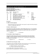
Страница 219: ...SHIH CHUAN ROAD PAN CHIAO CITY TAIPEI TAIWAN http www hybrex com AUTO TELECOM AUSTRALIA PTY LTD Unit 7 3 Gibbes Street Chatswood NSW 2067 All data and specifications are subject to change without notice P N 5503 4900 0000 ...

Отзывы: