Hudson 1955 Rambler Скачать руководство пользователя страница 120

 CLUTCH SECTION

The  is a single plate, dry disc type. A steel 
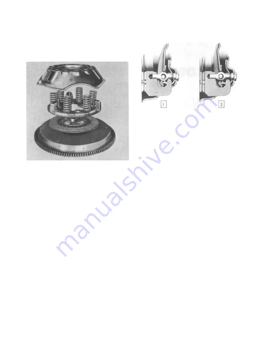
covet bolted to the flywheel contains the  drive 
plate, the pressure plate,  levers, and springs 
(Fig. 1).

FIGURE 1—Component Parts of Clutch

The clutch drive plate is spring cushioned with 
a facing riveted to both sides. The coil springs 
around the hub absorb the power shocks and 
cushion the driving mechanism.

 The clutch throw-out bearing is of the ball 
type, packed at time of manufacture, and 
requires no further lubrication.

 No adjustment for wear is provided in the  
clutch itself. An individual adjustment is built 
into the clutch cover to adjust the height of 
the release levers. This adjusting nut is locked 
in position and should never be disturbed unless 
the clutch assembly has been disassembled for 
the replacement of worn parts.

 When the clutch pedal is depressed, the 
release bearing is moved toward the flywheel and 
contacts the inner ends of the release levers. 
Each lever is pivoted on a floating pin which 
remains stationary in the lever and rolls across 
a short flat portion of the enlarged hole in the 
eyebolt. The outer ends of the eyebolts extend 
through holes in the stamped cover and are fitted 
with adjusting nuts to secure the levers in the 
correct position. The outer ends of the release 
levers engage the pressure plate lugs by means 
of fulcrums, which provide knife-edge contact 
between the outer ends of the levers and the lugs 
(Fig. 2).

REMOVING THE CLUTCH  ASSEMBLY

Always mark the  cover, pressure plate and 
flywheel on original production assemblies 
before removing, so that when they are reassembled

1. Engaged Position

2. Released Position

FIGURE 2—Clutch Lever

they will be in their same relative positions 
(Fig. 1).

CAUTION: 

When removing the clutch cover 

from the flywheel, loosen each cap screw 
a few turns until the spring tension on 
the cover has been released. The clutch 
cover is a steel stamping which could be 
sprung by incorrect removal, resulting in  
clutch chatter when reused.

CRANKSHAFT PILOT BUSHING

When a  assembly is removed from the flywheel, 
always inspect the crankshaft pilot bushing 
for scoring or loose condition. The bushing 
may be removed by using a tap. After the tap 
has bottomed in the bore, the bushing will be 
forced out. To provide initial lubrication for 
this bushing, coat lightly with a short fiber, 
medium wheel bearing grease.

CLUTCH DISASSEMBLY

The clutch cover and pressure plate are under 
spring tension at all times. Therefore, care 
must be exercised when a  cover assembly is 
disassembled. Place the  cover assembly in an 
arbor press with a hard wood block under the 
pressure plate. Have the block of such a 
length that the cover can move down and not 
interfere with the blocks. Place a wood block 
across the top of the cover so that it rests 
on the spring bosses and does not interfere 
with the eyebolt adjust. ing nuts (Fig. 3).
 Compress the clutch cover in the press 
until the clutch release levers are free. 
Remove the adjusting nuts (Fig. 3). Release 
the press slowly to prevent the springs from 
flying out.

CAUTION: 

When relieving the spring 

pressure, be sure the cover does not 
stick on the pressure plate bosses.

Содержание 1955 Rambler

Страница 1: ......

Страница 2: ......

Страница 3: ......

Страница 4: ......

Страница 5: ...ll aid in the installation of the cylinder head Fig 1 FIGURE 1 Guide Pin Installation to Install Cylinder Head Be sure that a sealing compound is used on all cylinder head cap screws Hornet and Wasp S...

Страница 6: ...Lock Installation Hornet and Wasp Series Wasp Hi Torque 6 Clearance permits removal of the manifolds without movement of the engine Rambler Series Exhaust pipe mounted to side of engine need not be re...

Страница 7: ...r Rambler Series Tool J 2814 illustrated in Figure 8 can also be adapted to the Hornet and Wasp Series by using the spacers from their respective guide installing tools The Hornet Series valve guides...

Страница 8: ...between the U D C mark and chalk mark on the inner timing mark radius 5 06 flywheel radius This distance should be 21 4 plus or minus 1 s for valve lash errors One tooth off timing on crankshaft spro...

Страница 9: ...ition Then set valves on the No 1 cylinder to 003 clearance Slowly rock the crankshaft back and forth 1 Marked Tooth on the Camshaft Sprocket 2 Marked Tooth on the Crankshaft Sprocket 3 91 2 Links or...

Страница 10: ...mer press the seal tightly into place After seal is in stalled recheck to make certain that the lip of leather is in good condition and not curled over FIGURE 17 Installing Timing Chain Cover Oil Seal...

Страница 11: ...move the radiator radiator grille fan assembly and intake and exhaust manifolds Pull the vibration damper pulley assembly after removing retaining cap screw Use Puller J 676 C for the Hornet Series Fi...

Страница 12: ...ings are positioned and retained in a limited working area by pins installed in the piston ring grooves Rambler Series The pistons are aluminum alloy cam ground having a larger diameter measured at ri...

Страница 13: ...ividually fitted to their respective bores The ring gaps for fitting rings are listed below Hornet 006 014 Wasp 004 009 Rambler 010 020 Piston Ring Installation Removal of glaze from the cylinder wall...

Страница 14: ...on pin The compression rings are of the twist design with an inner groove installed to the top of piston A conventional oil control ring is used in the third ring groove 1 Inner Groove Up 2 Oil Contro...

Страница 15: ...ing rod bushing is a hand push fit at room temperature 70 The piston pin fit in the piston is a hand push fit in a heated piston Heat piston in water or electric furnace to 200 F The piston pin bushin...

Страница 16: ...on for cylinder wall lubrication at low and idle speeds The notch on the top perimeter of the piston and the identification boss on the connecting rod Fig 33 must be installed to the front of the engi...

Страница 17: ...es and 001 to 0015 on Rambler Series To determine the amount of bearing clearance use a piece of Plastigage in the bearing cap as shown in Figure 36 Then tighten the cap to the torque specification to...

Страница 18: ...an assembly Replacement of vibration damper or fly wheel can be accomplished without rebalancing the complete assembly Crankshaft Main Bearings Main bearings are of the precision type having a steel...

Страница 19: ...al To operate this gauge remove the main bearing cap and place the gauge against the crankshaft journal Then release the plunger so that it is up against the journal and lock the adjusting screw in po...

Страница 20: ...Groove Locations Hornet and Wasp Series Rambler Series A hemp packing and L shaped neoprene rubber type rear main bearing oil seals are used A special tool J 1610 is required to install the hemp packi...

Страница 21: ...placement operations Fig 19 Tighten damper cap screw to 80 90 foot pounds torque Rambler Series The vibration damper is not adjustable The screws that retain the rubber are drawn up to a point where t...

Страница 22: ...sembly and fills the main horizontal oil gallery from which it is directed through drilled passages to lubri cate the camshaft bearings tappet assembly main and connecting rod bearings cylinder walls...

Страница 23: ...nnecting rod bearings The front camshaft bearing permits oil to flow onto the timing gear and chain assembly The valve tappets and piston pins are lubricated by crankshaft oil throw off and vapors CAU...

Страница 24: ...Intake Exhaust Stem to Guide Clearance Intake Exhaust Head Diameter Intake Exhaust Seat Angle Intake Exhaust Valve Face Angle Intake Exhaust Valve Spring Free Height Valve Spring Pressure Valve Open...

Страница 25: ...s Dry 7 Wasp Replaceable 4 0005 0015 2 4988 2 4998 003 009 No 3 Main Bearing 75 80 Ft Lbs Dry Rambler Replaceable 4 001 0015 2 4791 2 4798 003 008 Front Main Bearing 66 70 Ft Lbs Dry PRODUCTION PISTON...

Страница 26: ...Polarity Breaker Point Spring Tension Hornet and Wasp 17 20 Ounces Rambler 17 21 Ounces Spark Plugs Hornet Champion H 11 Torque 25 Ft Lbs Aluminum Head Wasp Champion H 10 Torque 30 Ft Lbs Cast Iron 25...

Страница 27: ...24 T E C H N I C A L S E R V I C E M A N U A L TECHNICAL SERVICE LETTER REFERENCE Date Letter No Subject Changes of informatin on Page No...

Страница 28: ......

Страница 29: ...t each for smooth and flat surfaces with a straight edge The cylinder block surface has two sleeve locating dowels to assist in lining up and holding position of cylinder head and gasket during instal...

Страница 30: ...angeable from cylinder bank to cylinder bank FIGURE 5 Valve Rocker Arm Assembly VALVES Figure 6 illustrates the valve arrangement Valve Springs Whenever valve springs are removed they should be tested...

Страница 31: ...eturn spring check valve assembly push rod socket and lock ring Fig 10 The tappet operates in a guide bore which has an oil passage drilled into the adjoining main oil galleries When the tappet is on...

Страница 32: ...ge at the check valve and its seat An intermittent noise at tappet is the result of dirt or chips stopping the check valve or a lack of oil flow into the body because of dirt A general tappet noise is...

Страница 33: ...han at the rear to permit easy removal and installation of the camshaft All camshaft bearings are lubricated under pressure The oil for lubrication is supplied through connecting drilled passages from...

Страница 34: ...osition The piston to bore clearances are 021 to 027 at top land 001 to 0015 top of skirt and 000 to 0015 bottom of skirt Fig 20 PISTON PINS Full floating type piston pins are mounted in a split bronz...

Страница 35: ...bore Then with an inverted piston push the ring down near the lower end of the ring travel area FIGURE 21 Burnishing Piston Pin Bushing When other than standard ring sizes are used rings should be ind...

Страница 36: ...ed The numbers are opposite the squirt holes and toward the outside of the banks in which they are located The squirt holes from connecting rods in one bank lubricate the cylinders in the opposite ban...

Страница 37: ...ring journals can be measured without removing the crankshaft from the engine block Various gauges are available for this purpose Always check both ends of the journal to note the taper Then rotate th...

Страница 38: ......

Страница 39: ...utilizing a factory packed sealed in car tridge shaft seal The seal gland springs hold the seal tight to the shaft The seal cartridge is non adjustable and serviced as an assembly only It is mounted...

Страница 40: ...d with cap screws and copper sealing washers Fig 5 FIGURE 5 Water Pump and Manifold Assembly Hornet V 8 Series Rambler Series The water pump impeller is installed in the slotted end of the pump shaft...

Страница 41: ...e coolant distribution manifold outlet A restricted passage permits the coolant to circulate through the water pump and cylinder block when the thermostat is closed thus by passing the radiator core A...

Страница 42: ......

Страница 43: ...e pulley forces air through the generator to cool the armature The generator output is regulated by the correct settings of the current and voltage regulator Lubrication At time of regular chassis lub...

Страница 44: ...ted for mechanical defects If the commutator is rough or worn it should be turned down in a lathe After turning the commutator the mica should be undercut to a depth of 1 32 When undercut ting the mic...

Страница 45: ...s specified Any other reading indicates faulty field coils or connections Check the motorizing draw Connect an ammeter and battery in series with the armature terminal and the frame Complete the field...

Страница 46: ...rcuit is completed through the contacts when they are closed and through a resistor when the contacts are opened When the voltage rises to a predetermined value there is sufficient magnetism created b...

Страница 47: ...ds from the regulator and connect an ammeter between them Remove the field lead from the regula tor and while operating at idle speed touch the field lead to the regulator base Increase the speed slow...

Страница 48: ...voltage change the armature spring tension by bending the hanger at the lower end of the spring Fig 3 Increase the spring tension to raise the closing voltage or decrease the tension to lower the volt...

Страница 49: ...with a low limit gauge on the contact side and next to the brass armature stop pin To adjust the operating amperage change the armature spring tension by bending the hanger at the lower end of the ar...

Страница 50: ...minal and the lead removed from the terminal Run the generator at a medium speed and perform the following operations After each test is completed reconnect whatever leads have been opened E L E C T R...

Страница 51: ...operating Reset regulator Dirty or sticking contacts Clean contacts Inoperative voltage regulator unit Remove regulator for an overhaul OPERATION EFFECT CAUSE AND REMEDY Read the voltmeter Remove the...

Страница 52: ...s dirty it may be cleaned with No 00 sandpaper Blow out all dust after cleaning NEVER USE EMERY CLOTH TO CLEAN COMMUTATOR If the commutator is rough out of round or has high mica it should be turned d...

Страница 53: ...t of round or burned bars With any of these conditions the commutator must be turned down in a lathe and mica undercut In addition when burned bars indicate an open circuit the open circuit condition...

Страница 54: ...OTE Adjustment need not be made if check shows value within range given When adjust ment is necessary adjust to specified value Current and voltage specifications apply only at operating temperatures...

Страница 55: ...tic field produced by the winding overcomes the armature spring tension pulls the armature down and the contact points separate This inserts resistance into the generator field circuit The generator f...

Страница 56: ...tings may be checked as outlined in the following sections FULLY CHARGED BATTERY AND A HIGH CHARGING RATE This indicates that the voltage regulator is not reducing the generator output as it should A...

Страница 57: ...lts the following steps should be taken in the sequence given 1 Bring voltage regulator to operating temper ature 2 Check voltage regulator 3 Check cut out relay 4 Bring current regulator to operating...

Страница 58: ...on never by reducing it If setting is too high adjust unit below required value and then raise to exact setting by increasing spring tension After each adjustment and before taking reading replace the...

Страница 59: ...ts close Note closing voltage Slowly increase turn in resistance to make sure points open Adjust closing voltage by turning adjust ing screw Fig 19 Turn screw clockwise to increase setting and counter...

Страница 60: ...tion Either one of two conditions which may exist will require tailoring Battery is being overcharged using too much water Battery remains undercharged 3 4 charge or less If the battery is being overc...

Страница 61: ...pe drive on Standard and Overdrive transmission and outboard type drive on Automatic transmission equipped units Model Series Type Transmission Number Hornet V 8 Ultramatic MCL 6132 Hornet 6 Standard...

Страница 62: ...exceed 10 volts maximum for each 100 amperes If the voltage loss is greater than the above limits the voltage should be measured over each part of the circuit to locate the resistance causing voltage...

Страница 63: ...Do not touch the points to the bearing surface or to the brush surface as the arc formed will burn the smooth finish If the lamp lights the coil connected to the commutator segment is grounded To test...

Страница 64: ...mounted on the starting motor specifica tions are Pull in coil 31 5 to 36 0 amperes at 3 0 volts Hold in coil 8 8 to 10 1 amperes at 3 0 volts Starting Switch Solenoid Hornet 6 and Wasp Series Inspect...

Страница 65: ...t the brushes and commutator The brushes should form good contact with the correct brush spring tension A dirty commutator can be cleaned with a strip of No 00 sandpaper held against the commutator wi...

Страница 66: ...r and causes listed under Failure to operate with high current draw High free speed with low developed torque and high current draw indicates Shorted fields There is no easy way to detect shorted fiel...

Страница 67: ...t would form an arc across the separating points The condenser prevents this because it has the ability or capacity to store up electrical energy The current instead of forming an arc flows into the c...

Страница 68: ...t be periodically removed from the engine and the following points checked Distributor Specifications Auto Lite Hornet V 8 Series Make Model Rotation Contact Gap Condenser Capacity Side Play End Play...

Страница 69: ...7 to 20 Ounces Measure with Scale Hooked on the Breaker Arm at the Contact and Pull on a Line Perpendicular to the Contact Face Take Reading as Contacts Separate The distributor cap should be thorough...

Страница 70: ...condenser lead or to defective connections This will cause burned points and ignition failure upon initial start and at high speeds CAPACITY is built into the condenser and is determined by the area o...

Страница 71: ...n limits it indicates either incorrect spring characteris tics or leakage in the vacuum chamber and lines The maximum advance is controlled by a stop on the vacuum chamber arm If the maximum advance i...

Страница 72: ...Vacuum Advance Make Model Advance Delco Remy 1112382 Clockwise at Drive End 31 to 37 Degrees 17 to 21 Ounces 022 18 to 23 Mfd Start at 2 0 Engine Degrees at 600 Engine R P M Intermediate 11 Engine Deg...

Страница 73: ...e in proportion to the vacuum The linkage be tween the diaphragm and the distributor stem is drawn into the vacuum units causing the distributor to rotate in its mounting to secure vacuum advance The...

Страница 74: ...ck with gauge again after tightening clamp screw THE CONTACT POINTS SHOULD BE CLEANED BEFORE ADJUSTING IF THEY HAVE BEEN IN SERVICE The cam or contact angle is the angle in degrees of cam rotation thr...

Страница 75: ...location Refer Oil Pump Removal and Replacement Engine Section Position engine in No 1 firing position and install distributor Rotate distributor until points just begin to separate Tighten clamp scr...

Страница 76: ...ssure light electric gauge receiver units for water temperature and fuel level clock and direc tional signal pilot lights 1 No Charge Indicator 2 Low Oil Pressure Warning Light 3 Left Turn Indicator P...

Страница 77: ...generator output rises above battery potential the current flow from the generator reverses the direction of flow in the charging circuit and the light goes out At this time the charge indicator ligh...

Страница 78: ...ult in propor tionately low gauge indication With the constant voltage regulator operating properly with input voltage normally varying from 5 6 to 8 0 volts input voltages in excess of 8 0 volts will...

Страница 79: ...e circuit to ground Indicator pointers should be on F and H marks To check temperature indicator gauge in cluster With a current flow of 06 amperes plus or minus 007 amperes through temperature gauge...

Страница 80: ...and voltage regulator Hornet and Wasp Se ries Operate the tank unit by hand The receiver must read empty with tank unit float in bottom position and full with tank float in top position Two ten foot...

Страница 81: ...ve cut in the switch housing to retain the cylinder Insert a stiff piece of wire or paper clip into the small hole as illustrated in Figure 50 Turn the key to the right ignition on position With the w...

Страница 82: ...LIGHT SWITCH Hornet and Wasp Series The main lighting switch is located at the left side of the dash panel between the radio speaker grille and windshield wiper control To remove the light switch ass...

Страница 83: ...wer 6 8 volts Rambler Series The Rambler Series front parking and direc tional light assemblies are mounted in the front section of the fender The parking lamp assembly less directional signal contain...

Страница 84: ...f the horns operate the horns and relay are not defective Then the horn button and lead should be thoroughly in spected The usual cause of continuous operation of the horns is a ground in the horn but...

Страница 85: ...core is satisfactory the turning action will be smooth On a damaged core although not notice able by visual inspection the turning action will be jerky and in a severe case the core will leap or jump...

Страница 86: ...75 075 Current Regulator Amperes 43 47 34 39 Adjust to 38 42 47 Adjust to 45 Air Gap 048 052 075 075 STARTING MOTOR SPECIFICATIONS Hornet V 8 6 Cylinder Rambler Make Auto Lite Auto Lite Auto Lite Delc...

Страница 87: ...46 T E C H N I C A L S E R V I C E M A N U A L...

Страница 88: ...ELECTRICAL WIRING DIAGRAMS...

Страница 89: ......

Страница 90: ......

Страница 91: ...ELECTRICAL WIRING DIAGRAMS...

Страница 92: ......

Страница 93: ......

Страница 94: ......

Страница 95: ......

Страница 96: ......

Страница 97: ......

Страница 98: ......

Страница 99: ......

Страница 100: ......

Страница 101: ......

Страница 102: ......

Страница 103: ......

Страница 104: ...ce with the instruction decalcoma nia attached however where no instruction decalcomania is present it should be serviced at every engine crankcase oil change More frequent service will be required wh...

Страница 105: ...pump in addition to supplying fuel pressure incorporates a vacuum booster pump which helps boost intake manifold vacuum for more stable windshield wiper operation Both type pumps have an air dome on...

Страница 106: ...8 Series combination fuel and vacuum pumps 3 1 2 to 4 1 2 P S I at 500 Engine R P M on the single action fuel pumps all Series Test is made with a pressure gauge connected to a T fitting at the carbur...

Страница 107: ...e and connect the fuel line to the tee fitting and a rubber hose to the remaining opening of the tee fitting Operate the engine at normal idle speed The fuel pump should fill a one pint measure held a...

Страница 108: ...s on top of pump arm should be parallel to straight edge Adjust by bending throttle connector at the upper angle Use Bending Tool T 109 213 Fig 9 Models WA1 2013 S WA1 2009 SA and WA1 2113 S The throt...

Страница 109: ...etighten the metering rod arm set screw in this position Fig 11 FIGURE 11 Adjusting Metering Rods WGD 2231 S Models WA1 2013 S WA1 2009 SA and WA1 2113 S Remove the metering rod and insert gauge Tool...

Страница 110: ...th the fast idle cam held in a normal idle position tighten throttle lever adjusting screw until it just seats against the cam Hold throttle lever closed and pull the cam back until first low step is...

Страница 111: ...normal idle position and adjust the idle speed screws until the throttle valves are just seated in closed position Crack the rear carburetor throttle valve and adjust the idle mixture screws 1 1 4 to...

Страница 112: ...n the intake manifold through the heat riser passages surrounding the carburetor risers in the manifold and then discharged into the right bank exhaust manifold A thermostatically controlled butterfly...

Страница 113: ...09 83 T 109 84 T 109 85 T 109 102 T 109 105 T 109 106 T 109 1175 T 109 126 T 109 193 T 109 213 T 109 241 Description 3 16 Float and Unloader Gauge 030 020 Wire Gauge 1 4 Float and Unloader Gauge Bendi...

Страница 114: ...12 FUEL CARBURETION EXHAUST SYSTEM TECHNICAL SERVICE LETTER REFERENCE Date Letter No Subject Changes of informatin on Page No...

Страница 115: ...I D 1 4 See Adjustments Inside Balanced Vent to Carburetor Air Horn Outside None Solid Needle Size No 42 Drill in Needle Seat No 67 Drill In Cover No 53 Drill In Cover No 53 Drill In Cover 0453 Slot...

Страница 116: ...2 I D 11 16 I D 1 3 8 I D 7 6 See Adjustments Outside No 10 Inside None Size No 46 Drill in Needle Seat No 65 Drill No 53 Drill No 53 Drill 0545 0555 Slot 165 030 120 124 No 46 Drill 1 2_11 2 Turns Op...

Страница 117: ...ousing No 42 Drill 030 7 32 Horizontal Slot 045 x 110 Top of Port 028 WGD 2231 S Installed Permanently Do Not Remove Well Jet No 70 Drill Vacumeter Type 0665 043 089 See Adjustments Plunger Type Mecha...

Страница 118: ...ip Nozzle Flush Type Discharge Jet Size 110 Inner Nozzle Seats in Slip Nozzle I D No 31 Drill Saxaphone Key Type Vacumeter Type 073 067 053 096 See Adjustments Plunger Type Adjustable Stroke Discharge...

Страница 119: ......

Страница 120: ...e cover pressure plate and flywheel on original production assemblies before removing so that when they are reassembled 1 Engaged Position 2 Released Position FIGURE 2 Clutch Lever they will be in the...

Страница 121: ...m over the ridge on the end of the lever Lift the lever and eyebolt off the pressure plate Fig 5 Clutch Pressure Plate Inspect the pressure plate to make sure that it is not cracked or scored Check on...

Страница 122: ...ed place the pressure springs in a vertical position on each spring boss In the Wasp and Rambler Series clutch the center spring boss in each group is not used Check the anti rattle springs in the clu...

Страница 123: ...es Clutch Lever Height 1 Adjusting Nuts FIGURE 11 Locking Adjusting Nuts CLUTCH DRIVE PLATE No repair of the clutch drive plate is recommended except replacement of facings A new plate should be insta...

Страница 124: ...at all times The clutch pedal to beam rod adjustment adjusted in production is made to provide proper leverage The outer end of the lever projects 5 6 on the Hornet Series and 1 2 on the Rambler Seri...

Страница 125: ...ck of lubrication in clutch linkage Broken clutch pressure springs Weak pressure springs Clutch Dragging A dragging clutch may be caused by Incorrect adjustment of clutch pedal Incorrect pressure leve...

Страница 126: ...12 FUEL CARBURETION EXHAUST SYSTEM TECHNICAL SERVICE LETTER REFERENCE Date Letter No Subject Changes of informatin on Page No...

Страница 127: ......

Страница 128: ...ransmission clutch shaft Always use two guide pins Tool J 1434 in place of the two upper cap screws so the transmission clutch shaft will slide out far enough to clear the clutch pilot bearing and clu...

Страница 129: ...e four cap screws that retain the rear bearing cap to the transmission case Tap the front end of the main shaft with a plastic or lead 1 Roller Bearings FIGURE 4 Bearing Rollers Inside the Clutch Shaf...

Страница 130: ...are marked accordingly The etching marks will correspond when properly assembled Fig 8 insuring smooth sliding action during shifting into second and third speed The Second Speed Low and Reverse Slid...

Страница 131: ...removed The transmission main shaft bushing 4 and felt ring 3 which acts as a lubricant wick for the bushing and the rear bearing cap oil seal 5 can be driven out to the rear of the bearing cap Fig 1...

Страница 132: ...lower the counter shaft gear to the bottom of the case Remove the reverse idler gear shaft by using a brass drift Fig 15 and lift the reverse idler gear out of the case FIGURE 15 Removing the Reverse...

Страница 133: ...until they can be washed To wash a bearing submerge it in a cleaning solution that is absolutely free of dirt and rotate it to flush away all oil and dirt Dry the bearing with care Carefully examine e...

Страница 134: ...install the shift levers Loading Countershaft Gear Needle Bearings To install the needle bearings in the counter shaft gear insert the spacer sleeve and dummy shaft in the gear Hold the spacer and sh...

Страница 135: ...Lock Plate FIGURE 24 Installing the Lock Plate Then place the Woodruff key in the main shaft keyway install the speedometer drive gear on the shaft tight against the rear bearing and install the snap...

Страница 136: ...Main Shaft Assembly Install the main shaft front snap ring using snap ring pliers Fig 27 FIGURE 27 Complete the Main Shaft Assembly by Installing the Front Snap Ring When the synchro clutch hub is pr...

Страница 137: ...clutch shaft end play The desired end play is 000 Friction Ring Clearance Measure the clearance of the friction rings using friction ring clearance gauge J 1410 These clearances should be between 060...

Страница 138: ...oupling Tap the coupling off the pinion shaft splines with a soft faced hammer Disconnect the crossmember from the support brackets at the side sills Then remove the crossmember and both front and rea...

Страница 139: ...lutch shaft and raising the rear end over the countershaft gear the shaft can be removed from the case Fig 35 FIGURE 35 Remove the Clutch Shaft Clutch Shaft Roller Bearings Inside the rear end of the...

Страница 140: ...to 677 x 578 Fig 42 FIGURE 42 Use a Dummy Shaft Machined to 677 x 5 7 8 to Remove the Countershaft With the dummy shaft in place lower the countershaft gears to the bottom of the case Reverse Idler Ge...

Страница 141: ...ould be replaced also Bearings Bearings must be handled with great care Wrap them in a clean cloth or paper until they can be washed To wash a bearing submerge it in a cleaning solution that is absolu...

Страница 142: ...countershaft gear load the countershaft gear by using a dummy shaft machined to 677 x 5 7 8 Figs 47 and 481 After installing the bearings in the coun tershaft gear and holding it in such a manner so a...

Страница 143: ...lling the Countershaft Gear Assembly in the Case shaft and install snap rings Then place the main shaft in the case from the rear Install the first and reverse sliding gear on the main shaft Fig 52 NO...

Страница 144: ...lubriplate will hold them in position Then install the front friction ring and the clutch shaft on the main shaft Fig 53 FIGURE 53 Installing the Clutch Shaft Now move the main shaft rear bearing into...

Страница 145: ...Ring Clearance Measure the clearance of the friction rings using friction ring clearance gauge J 1410 These clearances should be between 060 to 080 If less add steel shims as required between the rear...

Страница 146: ...ch Friction Rings 060 to 080 Second Speed Gear End Play 003 to 010 Clutch Shaft End Play 000 to 005 000 preferred Counter Shaft Gear End Play 003 to 006 Synchro clutch friction rings governed by steel...

Страница 147: ...motion can be done while the car is in the free wheeling stage The accelerator is de pressed so that the engine is driving the car and the control button is pulled out without depressing the clutch W...

Страница 148: ...throttle is applied will pull in third gear At Speeds Above 30 Miles Per Hour When the car speed is increased to governor cut in speed about 30 M P H the governor contacts close completing the govern...

Страница 149: ...OVERDRIVE 3 FIGURE 3 Above 30 Miles Per Hour the Governor Points Automatically Close Thus Closing the Governor Circuit and the Relay Which Energizes the Solenoid...

Страница 150: ...through the ignition interrupter points of the solenoid As soon as the solenoid is released the interrupter points are opened and the engine again fires normally The drive through overdrive is then d...

Страница 151: ...OVERDRIVE 5...

Страница 152: ...lunger has been permitted to enter the lock plate the contacts C in the solenoid actuating circuit are opened permitting a decreased flow of current through the holding coil to retain the plunger in p...

Страница 153: ...pening the points E and K in the kickdown switch and closes points J and L This at the same time breaks the governor circuit and completes the kickdown circuit The break in the governor circuit de ene...

Страница 154: ...re fuse in the overdrive relay for live circuits and clean contacts Connect test lead directly from the hot terminal on the circuit breaker to the terminal SOL or No 4 on the overdrive relay mounted o...

Страница 155: ...TE Due to the similarity of the Hornet Wasp and Rambler Series Overdrive Units in appearance and opera tion most of the illustrations shown refer to the Hornet Series The transmission and overdrive is...

Страница 156: ...s soon as the overdrive case has been pulled far enough away from the adapter to provide clearance insert a holding bolt through the adapter and bolt it to the transmission As you remove the overdrive...

Страница 157: ...shaft is being removed the rollers will drop out so keep one hand underneath to catch them Fig 18 1 Rollers 2 Main Shaft FIGURE 18 Remove the Main Shaft and Rollers To remove the ring gear from the m...

Страница 158: ...ter Rod Assembly and the Sun Gear and Collar can be Removed Together Removing the Solenoid Remove the two cap screws that hold the solenoid to the bearing adapter Turn the unit one quarter turn clockw...

Страница 159: ...e Main Shaft Bearing Remove the rear snap ring and tap the bearing out through the rear of the overdrive case The inner snap ring can then be removed This completes the disassembly of the overdrive un...

Страница 160: ...ing rough surfaces or any indications that the rollers may be slipping in the housing Inspect the roller cams on the free wheel hub for wear or grooving Fig 29 Test the action of the two cam retaining...

Страница 161: ...in the hearing adapter I Fig 32 I 1 Shifter Rod 2 Sun Gear FIGURE 32 The Shifter Rod and Fork Assembly is Installed With the Sun Gear and Collar Reinstalling the Pinion Cage and Cam Install the pinion...

Страница 162: ...Free Wheeling Rollers in Position until the Ring Gear and Main Shaft can be Installed FIGURE 36 Install the Main Shaft and Ring Gear on the Pinion Cage and Free Wheeling Cam The Speedometer and Gover...

Страница 163: ...ssive movement with no tension indicates that the shift rod is binding in the case Finally tighten the solenoid cap screws Completing the Reassembly of the Overdrive Install the main shaft snap ring T...

Страница 164: ...temperatures dilute the transmission and overdrive oil as required using light engine oil LUBRICATION CHART TRANSMISSION AND OVERDRIVE STANDARD CAPACITY U S MEASURES INCLUDING OVER DRIVE CAPACITY U S...

Страница 165: ......

Страница 166: ...e careful not to move the transmission levers out of the neutral position as the ad justment is being made DISASSEMBLING THE SHIFTING MECHANISM Standard and Overdrive Transmission Hornet and Wasp Seri...

Страница 167: ...es remove the three upper bolts and loosen the lower bolt Disconnect the steering gear jacket tube bracket at the instrument panel and remove the jacket tube and shifting assembly by raising it throug...

Страница 168: ...irt seals from the operating levers To complete the disassembly of the shifting mechanism on Hornet and Wasp Series equipped with standard or overdrive transmis sions remove the bearing housing from t...

Страница 169: ...rt Seal 12 Dirt Seal Spacer 13 Selector Pin 14 Dirt Seal Spacer Retainer 15 Dirt Seal 16 Gear Shift Operating Lever 17 Spacer 18 Inner Spring 19 Outer Spring 20 Operating Shaft 1 Selector Pin FIGURE 1...

Страница 170: ...g and bracket to the lower end of the steering jacket tube The entire bearing housing assembly can now be lowered into the engine compartment to facilitate further disas sembly Remove the dirt seal sp...

Страница 171: ...n the bearing housing to provide ease of assembly on the operating shaft Then assemble the bearing housing to the operating shaft Fig 19 Turn the operating shaft so that the hole in the shaft will ind...

Страница 172: ...ing the clevis two full turns and connect the clevis to the shift lever NOTE This adjustment will insure proper detent location in the transmis sion together with a full reverse engagement To adjust t...

Страница 173: ...ect the brake pedal and move the cover from the brake pedal rod Fig 22 Disconnect the transmission control rod by removing the cotter pin and lifting the rod out of the operating lever Fig 23 Disconne...

Страница 174: ...shift operating shaft from the upper end of the jacket tube Remove gear shift housing assembly Fig 27 Remove the starter switch rod from the operating lever Then remove the operating lever upper FIGUR...

Страница 175: ...1 1 Lever Knob 2 Gear Shift Lever 3 Pressure Spring Pin 4 Pressure Spring 5 Gear Selector Pointer Shroud 6 Gear Selector Dial 7 Gear Selector Pointer 8 Gear Selector Pointer Shaft 9 Gear Selector Poin...

Страница 176: ...r in the bearing housing Fig 31 I FIGURE 31 Install the Lower Spring in the Bearing Housing With the lower spring in position in the bearing housing compress the spring enough to install the operating...

Страница 177: ...operating lever Lift the housing assembly off of the U clamp bracket and separate the housing from the gear shift operating shaft Lower the operating shaft to remove the selector lever from the hole i...

Страница 178: ...14 TECHNICAL SERVICE MANUAL TECHNICAL SERVICE LETTER REFERENCE Date Letter No Subject Changes Information on Page No...

Страница 179: ......

Страница 180: ...due to gravity seepage It also may be used as a pump during a bleeding operation Inspection and Assembly of Master Cylinder When reconditioning a master cylinder clean all component parts in alcohol...

Страница 181: ...l enough fluid has passed through to expel all the air from the line Do this at each of the four wheels Watch the flow of fluid from the hose the end of which should be kept below the surface of the f...

Страница 182: ...ake lever must be in a full released position Adjust the brake pedal play to 1 4 to I 9 by adjusting length of master cylinder push rod Make a hard brake application and release the pedal At each whee...

Страница 183: ...support plate 1 Bend Here toward Support Plate 2 Attach Spring Scale here and Read Pressure It should be 15 Lbs FIGURE 7 Anchor Lip Adjustment PARKING BRAKE The parking brake applies the rear brake s...

Страница 184: ...vacuum reservoir tank is located in the intake manifold vacuum line Should a failure occur in the vacuum system this reserve supply of vacuum will allow the operator to make several power application...

Страница 185: ...it tube and vacuum reservoir tank It passes through the vacuum tube to the closed vacuum poppet Fig 131 BRAKES AND WHEELS HUBS AND DRUMS 7 FIGURE 12 Cross Section View Treadle Vac FIGURE 11 Hand Brake...

Страница 186: ...rake pedal is depressed the push rod and plunger move to the right in the power piston allowing the pivot arm and atmosphere poppet spring to close the atmosphere poppet After the atmosphere poppet cl...

Страница 187: ...a tion the reactionary force created within the power piston balances the physical pedal pressure and allows the power piston and rod plunger to reach a holding position When this occurs both the vacu...

Страница 188: ...can now be removed from the vacuum cylinder shell To insure proper reassembly scribe a line across the ouside of the vacuum cylinder shell and master cylinder housing Remove the three screws attaching...

Страница 189: ...ove vacuum poppet spring arm from piston plate Using pliers remove the two atmosphere 1 Valve 2 Rubber Seal 3 Retainer 4 Spring 5 Fitting FIGURE 19 Compensating Valve poppet retaining clips if necessa...

Страница 190: ...nspect all gasket contact areas Inspect piston plates for cracks and damaged threads Check plunger bore and poppet seats for any scratches or nicks Do not attempt to refinish bore Replace piston plate...

Страница 191: ...retaining ring in recess of cylinder bore use Tool J 4245 Truarc Pliers Place a new rubber seal on the compensating valve fitting Insert stem of new compensating valve into the threaded end of fitting...

Страница 192: ...22 Position new leather packing on the piston with the lip up place packing plate inside packing aligning holes in packing plate to holes in piston plate Cut a new cotton wick to correct length Dip it...

Страница 193: ...is not operating properly POSSIBLE DIFFICULTIES AND CORRECTIONS CONDITIONS AND PROBABLE CAUSE CORRECTIONS Hard Pedal Mechanical Condition Glazed Linings Grease or Brake Fluid on Lining Bind in Pedal...

Страница 194: ...ce Apply Lubriplate Check Operation and Lubriplate Check Alignment Clean Clean or Replace 16 TECHNICAL SERVICE MANUAL BRAKE SPECIFICATIONS Series Type of Mechanism Make Total Foot Braking Area Lining...

Страница 195: ...ountered the steering goemetry must be checked and set to specifications This condition can also be caused by bent steering arms with the result that the inside wheel on both turns either toes in or t...

Страница 196: ...al run out However the reading is taken at the inner vertical bead flange Fig 26 Static unbalance is an unequal distribution of weight around the center of rotation Fig 28 FIGURE 28 Static Unbalance W...

Страница 197: ...the nut and spindle Install the inner and outer hub caps REAR WHEEL BEARINGS AXLE SHAFT Rear Axle Shaft Bearing Removal Attach Rear Hub Puller 1 736 B to the rear wheel hub I Fig 32 and remove the hub...

Страница 198: ...The Rambler Series oil seal is installed behind the brake support plate Tighten the support plate bolts to 50 55 foot pounds torque on the Hornet and 30 35 foot pounds on the Wasp and Rambler Series...

Страница 199: ......

Страница 200: ...2 TECHNICAL SERVICE MANUAL...

Страница 201: ...axle tube and the rear axle stabilizer bar at the axle tube Roll the axle free from the car and disconnect the truss rods torque tube and propeller shaft from the rear axle The method of propeller sha...

Страница 202: ...play This practice will aid in setting the correct end play clearance at the time of reassembly Refer to section Checking and Adjusting Axle Shaft End Play Then remove the cap screws attaching the br...

Страница 203: ...e distances between their ends Fig 10 If the straight edges are parallel within 2 at a distance of 11 from the tube center the housing is serviceable Make this inspection two ways rizontally and vert...

Страница 204: ...driven out and the thrust block can be dropped out through the differential side gear Fig 14 Roll the differential pinion gears around on the side gears until they can be lifted out through the holes...

Страница 205: ...matched sets Inspect the ring gear attaching screws for elongation resulting from excessive tighten ing and replace any screws that are elongated Pinion Gear and Shaft Removal Hornet Series Inspect t...

Страница 206: ...ear or roughness and the pinion splines for damage caused by a worn or loose coupling Pinion Bearings Inspect pinion bearings cones cups and rollers for excessive wear over heating or scoring If repla...

Страница 207: ...side gear aligning the hole in the block with the differential pinion shaft Press differential pinion shaft in place and measure the clearance between the differen tial side gear and case This cleara...

Страница 208: ...ay be installed between the cone and the differen tial case For the Wasp or Rambler Series use Hornet pinion depth adjusting shims When side play is eliminated a slight bearing drag is noted Then inst...

Страница 209: ...and 010 shims to obtain various thickness combinations Various methods of determining the correct thickness of adjusting washer may be used Method No 1 Rear axle drive pinion gauge J 5223 A with side...

Страница 210: ...efore the new depth washer must be 005 thicker than the old one If the old washer is 123 the new one must be 128 In this case use a 125 washer plus a 003 shim totaling 128 Pinion Bearing Installation...

Страница 211: ...ies If the preload is too high increase the thickness of the shims if it is too low decrease the thickness Hornet Series Remove the spacer tool and install a new oil seal The companion flange is then...

Страница 212: ...al Side Bearings The rear axle differential bearings are pre loaded to compensate for the heat and loads during operation The correct preload is 004 to 008 The side bearings may be preloaded in two wa...

Страница 213: ...a thicker washer or shim between the pinion gear and bearing If the pattern is low on the ring gear tooth as in Figure 36 C the pinion is too close to the ring gear Then move the pinion away from the...

Страница 214: ...ecking and Adjusting Axle Shaft End Play Strike the end of each axle shaft with a lead hammer to seat the bearing cups against the support plate Attach axle shaft end play tool J 2092 to the end of on...

Страница 215: ...embly to hang freely with the shock absorbers fully extended Adjust the propeller shaft so the scribe mark is 2 to the rear of the transmission oil seal Tighten the coupling to 300 foot pounds torque...

Страница 216: ...rward This will permit the propeller shaft flange to be disconnected I Fig 41 I When reinstalling the propeller shaft use new locks on the companion flange nut Tighten the flange nuts 30 to 35 foot po...

Страница 217: ...ission have one piece tubular shafts incorporating a universal joint at the transmission end and a companion flange at 1 Propeller Shaft Coupling Oil Seal 2 Propeller Shaft Coupling Oil Seal Retainer...

Страница 218: ...t Shield 9 Spacer 3 Retainer Stud 10 Lock Nut 4 Bearing Cover 11 Felt Washer 5 Insulator 12 Felt Washer Retainer 6 Retainer 13 Lock Nut 7 Center Bearing FIGURE 47 Propeller Shaft Center Bearing and Re...

Страница 219: ...n The front of the torque tube has a coarse pitch thread on which the trunnion bracket operates This bracket is slotted on the underside and is provided with an adjustable clamp screw This clamp screw...

Страница 220: ...r the yoke member will be driven down to a point where it contacts the cross This will leave the end bearing protruding 1 Trunnions 2 End Bearings FIGURE 51 Removing End Bearing From the Yoke Carefull...

Страница 221: ...Wheel Hub to Shaft Nut Rear Brake Support Plate Screw Nut 50 55 105 110 125 150 30 35 70 80 180 190 50 55 50 55 55 60 90 100 250 300 30 35 Wasp Hydra Matic 70 80 160 165 30 35 REAR SPRING SPECIFICATIO...

Страница 222: ...12 lbs 14 lbs Shims 004 008 3 pts SAE 90 HYPOID 4 1 1 9 37 4 4 1 8 35 3 6 1 12 43 Semi Floating Hypoid 002 006 002 004 12 lbs 14 lbs Shims 004 008 3 pts SAE 90 HYPOID 3 8 1 9 34 4 4 1 8 35 3 3 1 13 43...

Страница 223: ......

Страница 224: ...NT COIL SPRINGS Spring Removal Hornet and Wasp Series The front coil spring may be removed using two front coil spring compressors J 5224 Remove the two rebound bumpers from the upper control arms and...

Страница 225: ...tion or removal of the spring compressor tools as outlined for the Hornet and Wasp Series Spring Installation Hornet and Wasp Series The spring may be compressed with two spring seats and threaded ro...

Страница 226: ...ng spindle support at the outer end Fig 8 Removal The upper control arm may be removed for replacement without removing the entire as sembly Remove the front spring then the front or rear arm by disco...

Страница 227: ...spring Discon nect at the lower shock absorber mounting spindle support and at the mounting bracket To install the lower control arms on the mounting bracket connect the shock absorber and tighten th...

Страница 228: ...upport by a steering spindle pivot pin and locked to the pivot pin with the steering arm End thrust on the spindle pivot pin is absorbed by ball bearings 7 between the upper end of the pivot pin and t...

Страница 229: ...osition in the spindle support shim stock will prevent damage to the grease seals and facilitate assembly Lubricate the bushings and top of pivot pin with viscous grease prior to assembly STEERING KNU...

Страница 230: ...ries Rambler Series C type spacers are installed between the lower control arm pivot bar and the shoulder of the mounting stud Increasing or decreasing the number or thickness of C spacers at either t...

Страница 231: ...nation is not adjustable independently of camber If incorrect the steer ing spindle support must be replaced Turning Radius Turning radius stop screws are provided on the pitman arm to provide adjustm...

Страница 232: ...TIGHTEN After each adjustment reinspect for proper mesh by shaking the pitman arm Steering Gear Removal Hornet and Wasp Series The steering gear complete with jacket tube is removed up through the acc...

Страница 233: ...the turning effort on the steering wheel must overcome the spring and oil pressure on the ends of the spool before the spool can be moved which results in a sense of feel for the driver Fig 20 The ri...

Страница 234: ...assembled When reassembling the valve use caution to prevent cutting the 0 rings The end plug should be reinstalled and tightened to the original marked position Final adjustment of the spool is accom...

Страница 235: ...FRONT SUSPENSION STEERING GEAR SECTION 13 FIGURE 22 Control Valve Assembly Hornet Series FIGURE 23 Control Valve Assembly Wasp Series...

Страница 236: ...til there is sufficient tension on the rubber cushions to prevent rattles and grease leakage and still permit free movement of the stud Over tightening the stud will cause poor recovery from turns and...

Страница 237: ...ring 2 Pump Shaft 3 Pump Shaft Seal 4 0 Ring Gasket The pump shaft oil seal is located in the pump body and is removed using combination pump shaft seal and power cylinder seal puller J 5503 Lubricate...

Страница 238: ...de Hold the valve against the spring tension and reinstall the snap ring Place the orifice plate in the recess of the valve above the snap ring Carefully install the valve assembly in the pump cover t...

Страница 239: ...ve vanes The shaft bearing is retained in the pump body with a Tru arc snap ring Remove the pump pulley shaft key The shaft and bearing is removed as an assembly after the snap ring is removed by tapp...

Страница 240: ...external leaks NOTE Air bubbles circulating through the pump will result in noise Normal ly three or four days operation is required to dissipate the air bubbles from the system This condition is bes...

Страница 241: ...ly Incorrectly Adjusted Incorrect Front Wheel Alignment Adjust Steering Replace Piston Rod Adjust Valve of Cylinder and Valve Assembly Realign Front Wheels Car Wanders from Straight Ahead without Forc...

Страница 242: ...to 1 8 FRONT SPRING SPECIFICATIONS Series Free Height Loaded Height Rate Lbs Per Inch After Loaded Weight Hornet 6 Cylinder Hornet V 8 Wasp Rambler Standard and Overdrive w o Air Conditioning Hydra Ma...

Страница 243: ......

Страница 244: ...should be opened slightly WINTER DRIVING The Weather Eye is a part of the engine cooling system and depends on normal engine operating temperature and air flow through the cowl ventila tor to heat th...

Страница 245: ...on To open the water control valve on the Rambler Series the control switch is pulled OUT to close it is pushed IN In both cases moving the control valves to the full open position allows the full flo...

Страница 246: ...to Heater Switch Terminal 7 Control Cable Conduit Clamp 4 Control Cable Threaded End FIGURE 5 Water Valve Control and Switch Assembly Rambler Series 1 Valve Outlet Tube to Upper Heater Core Tube 5 Ope...

Страница 247: ...the Hornet and Wasp Series water control valve serves as a counterbalance for the bellows spring to prevent movement of the valve without control operation COWL VENTILATOR DAMPER ADJUSTMENT Hornet and...

Страница 248: ...ter hopper box cover After the removal of the cover and the hoses the heater core is removed by sliding it forward and out of the heater hopper box In position it rests on the front flange of the heat...

Страница 249: ...fter removing the fan from the motor shaft The motor and mounting bracket is then accessible for further disassembly 1 Heater and Defroster Motor 2 Motor Mounting Plate 3 Motor Mounting Gasket 4 Heate...

Страница 250: ...8 TECHNICAL SERVICE MANUAL TECHNICAL SERVICE LETTER REFERENCE Date Letter No Subject Changes Information on Page No...

Страница 251: ......

Страница 252: ...uncomfort able to the passengers Air conditioning may be defined as the 8 Receiver 9 Check Valve 10 Solenoid By pass Valve 11 Filter and Liquid Indicator 12 Heater Core Heating Unit 13 Blower Motor an...

Страница 253: ...es have a significant effect on comfort within a fairly wide temperature range The normal comfort zone for people has been found to exist within a temperature range of 67 to 91 and the relative humidi...

Страница 254: ...place where tempera ture is to be lowered then causing condensation to take place where the discharged heat will not be objectionable the refrigeration cycle is accomplished DESCRIPTION AND OPERATION...

Страница 255: ...ALL SEASON AIR CONDITIONING SYSTEM 5 Figure 2 Freon 12 Temperature Pressure Relation Curve...

Страница 256: ...air conditioner would be turned to the High blower speed position When the air has been pulled down to a comfortable range the Low position can be used In the High or Low switch position the cooling o...

Страница 257: ...he cool air toward the lap area of the front seat passengers This position may be used when only these passengers are in the car or when driving into the hot sun Full open position is best suited for...

Страница 258: ...to keep the windshield defrosted Rambler Series The combination fan and water valve control knob is moved laterally to the right to intermediate positions to thermostatically control the heat as desi...

Страница 259: ...ol cables and housings are routed behind the glove box mounting panel The cowl ventilator cable and housing is routed through a hole and grommet in the dash panel Place the damper control knob in the...

Страница 260: ...med because the refrigerant dealt with is at high or low pressure at the time it is referred to as such The high side consist consists of the compressor line dis charge muffler in Rambler Series conde...

Страница 261: ...ener ally stated in terms of tons of refriger ation or B T U per hour A ton of refrigeration is the cooling effect resulting from the melting of 2 000 pounds of ice in 24 hours or one ton equivalent t...

Страница 262: ...ure 14 The Freon 12 refrigerant gas enters the compressor through the suction service valve at the same pressure as the gas in the evaporator It goes through a close mesh strainer upward through inlet...

Страница 263: ...high pressure vapor state To determine the level place your hand on the receiver the part contain ing the liquid will be colder than the vapor half while the system is in operation Fig 16 1 Fusible P...

Страница 264: ...agm equalizing or back pressure 1 The valve normally operates only during compres sor ON cycles During OFF cycles the evapora tor temperature as sensed by the power element which contains Freon 12 in...

Страница 265: ...let manifold Any loss of pressure in the evaporator would be corrected by the equalizer connection as it by passes from the outlet manifold back to the evaporator intake It assures operation of the co...

Страница 266: ...e blowers and the solenoid by pass valve are energized the valve is closed and normal air conditioning cycle takes place When the temperature of the evaporator reaches the frost point the solenoid by...

Страница 267: ...be and the by pass circuit is again used This method of control will serve to cycle the air conditioning system and prevent the evaporator core from frosting Indirectly it will tend to control the tem...

Страница 268: ...e temperature control thermostat and sole noid bypass valve are energized simultaneous ly The magnetic clutch plate on the compressor drive pulley is also energized and the clutch engages the drive pu...

Страница 269: ...the system to be used again should be capped immediately to prevent dirt and moisture from entering the line If caps are not available copper lines can be placed in an oven for a period of two or thr...

Страница 270: ...operation it should be capped The hand shut off valves do not close off pressure to the gauges They close each opening to the center connection and to each other Use of Gauge Manifold Set The gauge se...

Страница 271: ...18 from suction service valve port to compound gauge fitting on the gauge manifold set Fig 25 Install the gauge line from discharge service valve port fitting to the high pressure gauge fitting on the...

Страница 272: ...e of the gauge manifold With the drum in the upright position crack the drum valve slightly to admit the vaporized Freon gas from the top of the drum into the system Close the drum valve The internal...

Страница 273: ...in order to charge the refrigerant into the system in a vaporous state A bucket of hot water 125 F is adequate This will cause the liquid to vaporize as it leaves the drum Hot rags wrapped around the...

Страница 274: ...the stem backed all the way out Heat may be applied to the drum as outlined in the procedure of Partially Charg ing the System Open the Freon drum valve Charging with liquid refrigerant is done at th...

Страница 275: ...TION The oil in the container origi nally is packed moisture free and every effort should be made to maintain its status The oil will quickly absorb any moisture with which it comes in contact The con...

Страница 276: ...enters it will always end up in the condenser Air remains in the condenser and takes up valuable condensing space If the system is known to have the correct amount of refrigerant but during operation...

Страница 277: ...nd pass it slowly all around the joint It takes some time for any escaping refrigerant gas to be drawn through the exploring tube into the torch flame so this part of the work must not be hurried The...

Страница 278: ...bly is shown in Figure 30 and the components are shown in Figure 31 A complete seal kit is available for service replacements To replace the seal parts use the following procedure Run the compressor f...

Страница 279: ...ressure on the crankcase unless the pulley and clutch is held firmly in place by the spacer cap screw and lock plate Excessive crankcase pressure and a defective snap ring will allow the seal to be bl...

Страница 280: ...s use new gaskets Before assembling dip in clean refrigerant oil Replace the suction valve leaves with the leaves included in the replacement kit Dip the valve leaves in clean refrigerant oil Install...

Страница 281: ...or pulley and or idler shaft or power steering pulley Remove the compressor from the compressor mounting bracket The compressor and idler shaft or power steering bracket can be removed from the engine...

Страница 282: ...any air from the system by cracking or slightly opening the high pressure gauge to the center connection of the gauge manifold set and bleed the air to the atmosphere This of course is done with the s...

Страница 283: ...two high pressure and two suction or low pressure and cap lines After installing new heat exchanger install gauge manifold set Evacuate the system and leak test Install charge Start engine and operat...

Страница 284: ...ing tube must be in between the fins of the evaporator core To remove the control thermostat remove the right right hand air duct The thermostat is now accessible for removal Removal of Blower Fan and...

Страница 285: ...ve A faulty by pass valve will not close or hold closed under pressure This will be noted by lack of cooling The refrigerant is being by passed Temperature Control Thermostat A faulty thermostat will...

Страница 286: ...tor Fan Belt Slipping Excessive Charge Engine Over Heating Restriction in Discharge Line Restrictions on Outlet Lines of Condenser Restriction in Check Valve Restriction in Receiver Expansion Valve Su...

Страница 287: ......

Страница 288: ......

Страница 289: ......

Страница 290: ...TECHNICAL SERVICE MANUAL TECHNICAL SERVICE LETTER REFERENCE Date Letter No Subject Changes Information on Page No...

Страница 291: ......

Страница 292: ......

Отзывы: