20
LP- 428 REV. 9.2.14
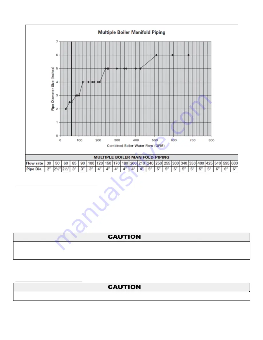
Figure 6
– Multiple Boiler Manifold Piping
H. FILL AND PURGE HEATING SYSTEM
Attach the hose to balance and purge hose connector or drain valve and run hose to nearest drain.
Close the other side of the balance and purge valve or the shut off valve after the drain.
Open first zone balance and purge or drain valve to let water flow out the hose. If zone valves are used, open the valves one
at a time manually. (
NOTE:
You should check the valve manufacturer’s instructions prior to opening valves manually, so as
not to damage the valves.)
Manually operate fill valve regulator. When water runs out of the hose, you will see a steady stream of water (without bubbles).
Close balance and purge valve or drain to stop the water from flowing. Disconnect the hose and connect it to next zone to be
purged.
Repeat this procedure for additional zones (one at a time).
For installation that incorporates standing iron radiation and systems with manual vents at the high points, follow previous section and,
starting with the nearest manual air vent, open until water flows out. Then close vent. Repeat procedure, working your way toward the
furthest air vent. It may be necessary to install a basket strainer in an older system where larger amounts of sediment may be present.
Annual cleaning of the strainer may be necessary.
Upon completion, make sure that the fill valve is in the automatic position and each zone balance and purge or shut off is in an open
position and zone valves are positioned for automatic operation.
I. FREEZE PROTECTION FLUIDS
Use only inhibited glycol solutions which are specially formulated for hydronic systems. Ethylene glycol is toxic and can attack gaskets
and seals used in hydronic systems. Glycol mixtures should not exceed 50%.
1. Glycol in hydronic applications is specially formulated for this purpose, and includes inhibitors that prevent the glycol from attacking
metallic system components. Make certain that the system fluid is checked for the correct glycol concentration and inhibitor level.
Содержание MODCON1000
Страница 40: ...40 LP 428 REV 9 2 14 E GAS VALVE Figure 22 Mod Con 1000 Gas Valve ...
Страница 46: ...46 LP 428 REV 9 2 14 Figure 25 Figure 26 Cascade Resistor Plug Installation Detail ...
Страница 47: ...47 LP 428 REV 9 2 14 Figure 27 Mod Con Cascade Master and Follower Wiring ...
Страница 48: ...48 LP 428 REV 9 2 14 Figure 28 Mod Con Internal Connection Diagram LP 428 K ...
Страница 70: ...70 LP 428 REV 9 2 14 Figure 31 MOD CON 1000 External Parts Blowout ...
Страница 71: ...71 LP 428 REV 9 2 14 Figure 32 MOD CON 1700 External Parts Blowout ...
Страница 72: ...72 LP 428 REV 9 2 14 Figure 33 ...
Страница 73: ...73 LP 428 REV 9 2 14 Figure 34 LP 445 S ...
Страница 74: ...74 LP 428 REV 9 2 14 Figure 35 LP 428 V ...
Страница 75: ...75 LP 428 REV 9 2 14 Figure 36 ...
Страница 78: ...78 LP 428 REV 9 2 14 ...
Страница 79: ...79 LP 428 REV 9 2 14 ...
Страница 80: ...80 LP 428 REV 9 2 14 MAINTENANCE NOTES ...


