


Shenzhen Hpmont Technology Co., Ltd.
Chapter 7 Elevator Application Guidance
HD5L Series Controller User Manual V1.4
―
79
―
Chapter 7
Elevator Application Guidance
7.1
Basic Commissioning Procedures
7.1.1
System Analysis and Wire
It is recommended to analyze the actual application requirements before the wiring design.
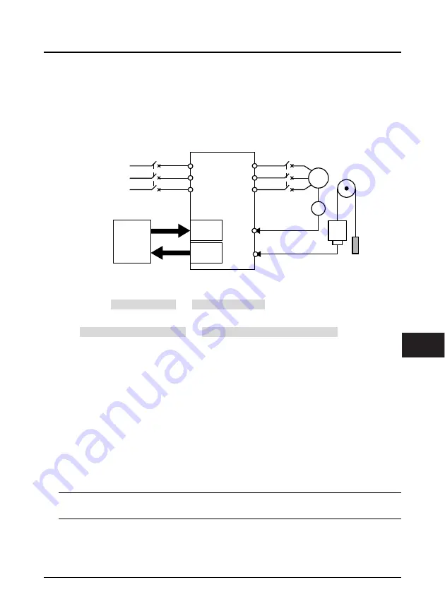
Basic configuration for elevator system with HD5L is shown in Figure 7-1.
Figure 7-1 Elevator system
7.1.2
Set Basic Parameters
1. Correctly set F00.00 (motor type) and F00.01 (control mode) according to motor type.
2. Set Group F07 for the asyn. motor, set Group F10 for the syn. motor.
3. Set F00.02 (Rated speed of elevator) and F00.04 (Mechanical parameters of motor) according to the
elevator requirement and motor parameters.
4. Set encoder relevant parameters of Group F11 according to the encoder configured to motor.
5. Set digital I/O terminal parameters of Group F12 according to the actual wiring.
6. Set the parameter according to the actual running mode:
•
Terminal MS running mode:
Set MS parameters of Group F05 according to the actual requirement
of elevator and the controller. Set Acc / Dec curve parameters of Group F03 according to the
elevator speed.
•
Terminal analogue running mode:
Set analogue curve parameters of Group F04 and analogue I/O
terminal parameters of Group F13 according to the actual requirement of elevator and the
controller. The bigger Acc / Dec curve parameters of Group F03 are set, the quicker HD5L catch the
speed command of elevator controller.
7.1.3
Motor Auto-tuning
Note:
The crane car is needed for the rotary auto-tuning but not for the stationary auto-tuning.
MCCB
U
V
W
L1
L2
L3
R
S
T
M
HD5L
Car
Counter
weight
Input
Terminal
Output
Terminal
Elevator
Controller
Three-phase
power supply
380V 50/60Hz
Contactor
Weigh signal feedback
Speed feedback
PG
7