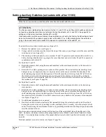
4. Set Up and Calibration Procedures - Setting Auxiliary Switches (actuators mfd. pre-1/1/03)
72
10260S HercuLine® Actuator Installation, Operation and Maintenance Manual
Revision 5
7/07
0%
100%
8 (SW1 COM)
9 (SW2 COM)
7
NC
NC
15
5
14
Left hand
Pointer scale
SW#1
SW#2
End of travel limit switch settings
Clockwise and counterclockwise rotation is the direction of the output shaft when facing the end
of the shaft. As shown, clockwise rotation of the output shaft activates SW#1 (at 0% on left hand
pointer scale) and CCW rotation activates SW#2 (at 100% on left hand pointer scale). Terminal
numbers are next to circles (see
Figure 13
page 26).
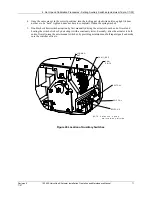
Figure 21 End of Travel Limit Switch Settings
Figure 22 Auxiliary Switch Settings
Содержание HercuLine 10260S
Страница 10: ......
Страница 94: ......
Страница 121: ......
Страница 122: ...Honeywell Field Solutions Honeywell Inc 512 Virginia Drive Fort Washington PA 19034 ...

