3. Installation - Electrical Installation
24
10260S HercuLine® Actuator Installation, Operation and Maintenance Manual
Revision 5
7/07
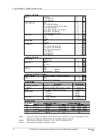
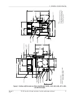
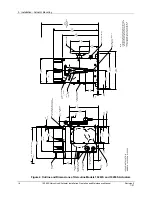
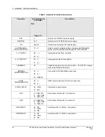
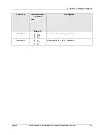
Table 3 Actuator Terminal Connections
Connection
Terminal Numbers
and LABEL
See
Figure 13.
Descriptions
HOT
L
Hot wire for 120/240 Vac mains supply
NEUTRAL
N - 3
Neutral wire for 120/240 Vac mains supply
PE
Ground
Ground wire connection for mains supply
AUTO/MANUAL
SWITCH CONTACT
10 – 11
Switch contact to indicate setting of actuator AUTO/MANUAL
switch. Switch is closed when actuator is “NOT-IN-AUTO”
4 – 20 INPUT
28 (-)
29 (+)
Analog signal input from controller.
4 – 20 OUTPUT *
30 (-)
31 (+)
Analog signal output from actuator.
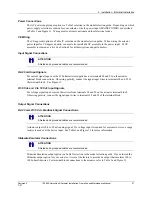
FEEDBACK 32
Feedback signal used in conjuction with 4 – 20 OUTPUT voltage
when using Slidewire Emulation.
MODBUS
COMMUNICATION
33 (-)
34 (+)
35 SHIELD
Connection for RS485 Modbus loop wires.
HART
COMMUNICATION
28 (-)
29 (+)
HART communication is for 4-20 mA input only.
DIGITAL INPUT
36 COM
37 INP
Customer’s contact closure.
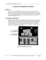
SW1
6 - 7 SW1 NC
9
SW1 COM
14 SW1 NO
End-of-travel limit switch 1 connections
SW2
4 - 5 SW2 NC
8
SW2 COM
15 SW2 NO
End-of-travel limit switch 2 connections.
SW3/RELAY1
16 NC
17 COM
18 NO
Auxiliary switch 3 or Relay 1 connections.
SW4/RELAY2
19 NC
20 COM
21 NO
Auxiliary switch 4 or Relay 2 connections.
Содержание HercuLine 10260S
Страница 10: ......
Страница 94: ......
Страница 121: ......
Страница 122: ...Honeywell Field Solutions Honeywell Inc 512 Virginia Drive Fort Washington PA 19034 ...

