4. Set Up and Calibration Procedures - Digital Input Set Up Group
46
10260S HercuLine® Actuator Installation, Operation and Maintenance Manual
Revision 5
7/07
Digital Input Set Up Group
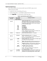
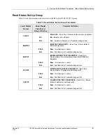
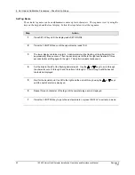
Table 15 lists the parameters and selections availible for the SET DIGINP group.
Table 15 Digital Input Set Up Group Parameters
Lower Display
Prompt
Upper Display
Selections or
Range of Setting
Parameter Definition
DIGINP
NONE
UP
DOWN
USER
Digital Input State
—Selects the position of the actuator in
response to a digital input signal (contact closure).
None
—No action by the actuator.
Up
—Actuator motor moves to full scale value.
Down
—Actuator motor moves to zero value.
User
selected value
—Actuator motor moves to a customer-
selected value.
* Allows setting of End Position Value.
EndPos *
0 – 100.
(in percent)
END POSITION VALUE
—(DIGINP USER only) Selects the
motor position you want the actuator to go to when digital
input signal present (contact closure).
Display Set Up Group
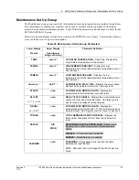
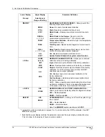
Table 16 lists the parameters and selections availible for the SET DISPLA group.
Table 16 Display Set Up Group Parameters
Lower Display
Prompt
Upper Display
Selections or
Range of Setting
Parameter Definition
DECMAL
8888
[default]
or
888.8
DECIMAL POINT LOCATION
—This selection determines
where the decimal point appears in the display.
None
One Place
Note: Be sure the selection agrees with the value to be
displayed. If display value requires 4 whole digits, the
decimal will not show.
EUNITS
PCNT
DEG
UNITS DISPLAY
—Selects the units of the position display.
Percent
—Shows actuator position as a percentage of span.
(0 to 100%)
Degrees
—Shows the actuator position in degrees of
rotation. (0 to 90
°
). Note: Not accessible when characterizer
= CUST.
Continued on next page
⇒
Содержание HercuLine 10260S
Страница 10: ......
Страница 94: ......
Страница 121: ......
Страница 122: ...Honeywell Field Solutions Honeywell Inc 512 Virginia Drive Fort Washington PA 19034 ...


