background image

GR4000 Installation Guide Version 1.00 - Preliminary 

520-10-014-20X  

169 

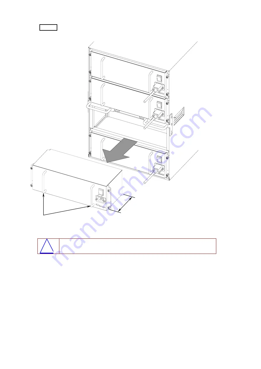
 Step 4 


 Hold the handles of the power supply unit, and remove the power supply 

unit by pulling its handle towards you.  


Figure 5.4-16


Power supply unit removed from the device 

!


Caution:  The GR4000-320E (AC) weighs approx. 10kg and its depth is 148mm. Be 

careful not to drop it when handling it, otherwise you may be injured. 


Handles  

148 

Unit

mm 

Содержание GR4000 Series

Страница 1: ...Hitachi Gigabit Router GR4000 Series Installation Guide Version 1 00 Preliminary ...

Страница 2: ...rnetworking hitachi com European Office Whitebrook Park Lower Cookham Road Maidenhead Berkshire SL6 8YA United Kingdom Tel 44 16 28 58 54 58 FAX 44 16 26 58 57 14 Germany Office Dornhofstrasse 34 D 63263 Neu Isenburg Germany Tel 49 6102 2999 50 FAX 49 6102 2999 63 All brands and product names are trademarks or registetred trademarks of their respective holders Copyright 2003 2004 Hitachi Ltd All R...

Страница 3: ...k Interface Module NIF 42 1 6 1 Single size NIF 42 1 6 2 Double size NIF 51 1 7 Memory Card and Main Storage 53 1 7 1 Memory Card MC256 53 1 7 2 Main Storage MS256 53 1 8 GBIC and SFP 54 1 8 1 GBIC 54 1 8 2 SFP 56 2 PREPARING FOR INSTALLATION 57 2 1 Flow of the Preparations 58 2 2 Setting Conditions for the GR4000 Models 59 2 3 Considerations regarding the carriage of GR4000 Models 60 2 3 1 GR4000...

Страница 4: ...0E1 into a rack 101 4 4 2 Installation of the GR4000 80E2 into a rack 104 4 4 3 Installation of the GR4000 160E1 into a rack 106 4 4 4 Installation of the GR4000 60E2 into a rack 110 4 4 5 Installation of the GR4000 320E AC GR4000 320E DC into a rack 112 4 5 Attachment Detachment of Power Cables 115 4 5 1 Attachment Detachment of GR4000 80E1 Power Cables 115 4 5 2 Attachment Detachment of GR4000 1...

Страница 5: ...ion Replacement of Power Supply Units 156 5 4 1 Case of GR4000 80E1 156 5 4 2 Case of GR4000 160E1 161 5 4 3 Case of GR4000 320E AC 166 5 4 4 Case of GR4000 80E2 172 5 4 5 Case of GR4000 160E2 GR4000 320E DC 176 5 5 Additional Installation Replacement of Basic Control Units 180 5 6 Additional Installation Replacement of Packet Routing Units 185 5 7 Additional Installation Replacement of Network In...

Страница 6: ...ing Equipment DHCP Dynamic Host Configuration Protocol Diff serv Differentiated Services DLCI Data Link Connection Identifier DNS Domain Name System DR Designated Router DSAP Destination Service Access Point DSCP Differentiated Services Code Point DTE Data Terminal Equipment DVMRP Distance Vector Multicast Routing Protocol E Mail Electronic Mail ES End System FCS Frame Check Sequence FDB Filtering...

Страница 7: ...ol Independent Multicast PIM DM Protocol Independent Multicast Dense Mode PIM SM Protocol Independent Multicast Sparse Mode PPP Point to Point Protocol PPPoE PPP over Ethernet PRED Predicted Random Early Detection PRI Primary Rate Interface PRU Packet Routing Module PVC Permanent Virtual Channel Connection Permanent Virtual Circuit QoS Quality of Service RA Router Advertisement RDI Remote Defect I...

Страница 8: ...n broad general use as the name of standards specifying QoS L2 user priority Acronyms in GR4000 BCU Basic Control module CP Multilayer Control Processor MC Compact flash Memory Card NIF Network Interface Module PRU Packet Routing Module PS Power Supply RM Routing Manager S W Software Numerical Conversion 1KB 2 to the 10th power 1 024 bytes 1MB 2 to the 20th power 1 048 576 bytes 1GB 2 to the 30th ...

Страница 9: ...rrectly and safely without injuring yourself and others or damaging equipment assets Below are the symbols and their meanings Note A note is informational in nature Unlike cautions and danger notices notes are not related to the physical injury or a damage to the device Caution If you ignore a caution and mistreat the GR4000 or GS4000 you could cause physical damage to the router or surroundings o...

Страница 10: ... GR4000 or GS4000 on a desk lay it down horizontally in it s normal orientation If you stand it vertically or lean it against a wall it could fall and be damaged and potentially cause injury Do not remove the cover when it is operating since this can cause you to receive a shock Make sure that the device is in a stable secure position when mounting it into a rack If you try to install it without a...

Страница 11: ...ust be moved by qualified personnel using the proper tools Allowing unqualified personnel to move the device could cause damage to the device itself and a person handling it Model Weight GR4000 160E1 GS4000 160E1 Approx 80kg GR4000 160E2 GS4000 160E2 Approx 70kg GR4000 320E AC GS4000 320E AC Approx 130kg GR4000 320E DC GS4000 320E DC Approx 120kg Also when handling these devices make sure that you...

Страница 12: ...use an electric shock When replacing a power supply unit or installing an additional one remove the power cable from the power supply unit to be replaced Even if the power switch is turned OFF electricity is still present in the cables connected to the device which can cause a fire or electric shock When using a DC power cable attach an insulating sheath at the cable terminal Using a unsheathed DC...

Страница 13: ...shock If the power cable is ever damaged so that the wires underneath the covering are visible or cut stop using it and ask a maintenance person to replace it Using damaged cables could easily cause a fire or an electric shock Do not use adapters to connect multiple power cables to the same outlet Doing this can cause a fire or cause a circuit breaker to trip due to an overloaded circuit This devi...

Страница 14: ...r turn off the power switch while the memory card is being accessed If so you could permanently damage the memory card When moving the device do not hold the handle of a power supply unit These handles are not intended for this purpose and could break off causing the power supply unit and the device to fall which could cause injury to you The device itself could also be damaged which could cause a...

Страница 15: ...ype Weight Approx AC Power Supply Unit for models GR4000 80E1 GR4000 160E1 GS4000 80E1 and GS4000 160E1 5 kg AC Power Supply Unit for models GR4000 320E AC and GS4000 320E AC 10 kg DC Power Supply Unit for models GR4000 80E2 GS4000 80E2 4 kg DC Power Supply Unit for models GR4000 160E2 GR4000 320E DC GS4000 160E2 and GS4000 320E DC 7 kg Basic Control Unit BCU 4 kg Packet Routing Switching Unit PRU...

Страница 16: ...thium battery for the real time clock Mishandling this battery may cause overheating damage or in an extreme case explosion or fire Do not remove the battery attempt to disassemble it or expose it to temperatures of over 100 C 212 F Also do not incinerate or dispose of this battery in water Remove dust on or around the device regularly Accumulated dust can choke off ventilation to components cause...

Страница 17: ...y with the instructions written on the label put on a packet routing switching unit See below No Pile Up Not For Handling Caution Do not hold the area marked with in the figure below when mounting or removing a Packet Routing Unit PRU from a GR4000 model or a Packet Switching Unit PSU from a GS4000 model Doing so might deform the outer frame of the PRU or PSU and the NIF might be damaged if you tr...

Страница 18: ... dispose of exhausted devices or boards in an environmentally responsible manner and as required by your local regulations The GR4000 or GS4000 contains lithium batteries circuit boards containing copper lead and tin cables and connectors all of which can be recycled Do not install optional components or accessories for the GR4000 or GS4000 on devices other than the GR4000 or GS4000 Doing so could...

Страница 19: ...r presents the overview of each component of the GR4000 models 1 1 Chassis 1 2 Fan Unit 1 3 Power Supply Unit 1 4 Basic Control Module BCU 1 5 Packet Routing Module PRU 1 6 Network Interface Module NIF 1 7 Memory Card and Main Storage 1 8 GBIC and SFP ...

Страница 20: ... slots Slot for a fan unit 1 slot 1 Outer Appearance Figure 1 1 1 GR4000 80E1Front View NOTE The network interface modules NIF must be mounted into the packet routing modules PRU See the section 1 5 Packet Routing Module PRU for the details about the packet routing module NOTE Do not install optional components into the vacant slots above Slot for a fan unit Slot for BCU Slot for PRU Front panel S...

Страница 21: ...y 520 10 014 20X 3 Figure 1 1 2 GR4000 80E1 Rear View 2 Slot Numbers Shown below are the numbers of the slots for each component unit of GR4000 80E1 Figure 1 1 3 GR4000 80E1 Slot Numbers POW0 POW1 Front View PRU0 PRU1 BCU0 NIF0 NIF2 NIF3 NIF1 F A N 0 ...

Страница 22: ...witches of other component units Figure 1 1 4 GR4000 80E1 Front Panel Table 1 1 1 LED Indications on the GR4000 80E1 Chassis Name Color Role Action Status FAN0 Green Red Shows the action status of FAN0 Green ON running in normal condition Red ON failure detected BCU0 Green Yellow Red Shows the action status of of BCU0 Green ON operation possible Yellow ON locked out Green blinking in preparation f...

Страница 23: ...ces other than the GR4000 or GS4000 Doing such a thing causes a fire or an electric shock Rack Mounting Bracket R Rack Mounting Bracket L GR4000 80E1 Rack Mounting Brackets 2 types one R type bracket and one L type bracket These are used to install the body of GR4000 80E1 into a 19 inch cabinet rack Screws M4 6 6 pieces These are used to attach the rack mounting brackets to the body of a device ...

Страница 24: ... power supply 2 slots Slot for a fan unit 1 slot 1 Outer Appearance Figure 1 1 6 GR4000 80E2 Front View NOTE The network interface modules NIF must be mounted into the packet routing modules PRU See the section 1 5 Packet Routing Module PRU for the details about the packet routing module Slot for a fan unit Slot for BCU Slot for PRU Rack mounting bracket R Rack mounting bracket L Front panel ...

Страница 25: ...14 20X 7 Figure 1 1 7 GR4000 80E2 Rear View 2 Slot Numbers Shown below are the numbers of the slots for each component unit of GR4000 80E2 Figure 1 1 8 GR4000 80E2 Slot Numbers Front Back PRU0 PRU1 BCU0 NIF0 NIF2 NIF3 NIF1 F A N 0 POW POW Slot for power supply ...

Страница 26: ...r Role Action Status FAN0 Green Red Shows the action status of FAN0 Green ON running in normal condition Red ON failure detected BCU0 Green Yellow Red Shows the action status of of BCU0 Green ON operation possible Yellow ON locked out Green blinking in preparation for startup Red ON failure detected OFF BCU powered off BCU exchangeable PRU0 NIF1 0 Green Yellow Red Shows the action status of PRU0 G...

Страница 27: ... for power supply 4 slots Slot for a fan unit 2 slot 1 Outer Appearance Figure 1 1 10 GR4000 160E1 Front View NOTE The network interface modules NIF must be mounted into the packet routing modules PRU See the section 1 5 Packet Routing Module PRU for the details about the packet routing module Slot for BCU Slot for PRU Slot for PRU Slot for a fan unit Slot for power supply unit Front panel ...

Страница 28: ... GR4000 160E1 Rear View 2 Slot Numbers Shown below are the numbers of the slots for each component unit of GR4000 160E1 Figure 1 1 12 GR4000 160E1 Slot Numbers P O W 0 P O W 1 P O W 2 P O W 3 Front PRU0 PRU2 PRU3 PRU1 BCU0 BCU1 NIF0 NIF2 NIF4 NIF6 NIF7 NIF5 NIF3 NIF1 F A N 1 F A N 0 ...

Страница 29: ...dundant power source should be installed should not be installed 3 LED Light Emitting Diode and Switches The LED of a chassis indicates the action status of a fan unit BCU and PRU The LED is attached to the fan unit and the status indicated by the LED differs depending on the type of a device or the position where the fan unit is installed As for the status indicated by the each LED of a chassis s...

Страница 30: ...GR4000 Installation Guide Version 1 00 Preliminary 12 520 10 014 20X Figure 1 1 13 GR4000 160E1 Front Panel Front panel LED LED ...

Страница 31: ...the action status of PRU1 PRU2 NIF5 4 Shows the action status of PRU2 PRU3 NIF7 6 Green Yellow Red Shows the action status of PRU3 Green ON operation possible Yellow ON locked out Green blinking i n preparation for startup Red ON failure detected OFF BCU powered off BCU exchangeable 4 Accessories Figure 1 1 14 GR4000 160E1 Accessories NOTE Do not install the optional components of GR4000 or GS4000...

Страница 32: ...supply 4 slots Slot for a fan unit 2 slots 1 Outer Appearance Figure 1 1 15 GR4000 160E2 Front View NOTE The network interface modules NIF must be mounted into the packet routing modules PRU See the section 1 5 Packet Routing Module PRU for the details about the packet routing module Slot for PRU Slot for a fan unit Slot for BCU Slot for PRU Rack mounting bracket R Rack mounting bracket L Front pa...

Страница 33: ...0 160E2 Rear View 2 Slot Numbers Shown below are the numbers of the slots for each component unit of GR4000 160E2 Figure 1 1 17 GR4000 160E2 Slot Numbers PRU0 PRU2 PRU3 Front Back PRU1 BCU0 BCU1 NIF0 NIF2 NIF4 NIF6 NIF7 NIF5 NIF3 NIF1 POW1 POW0 F A N 1 F A N 0 Slot for a power supply unit ...

Страница 34: ...it and the status indicated by the LED differs depending on the type of a device or the position where the fan unit is installed As for the status indicated by the each LED of a chassis see Table 1 1 4 Refer to the section 1 3 Power Supply Unit 1 4 Basic Control Module BUC or 1 6 Network Interface Module NIF for the LED and switches of other component units Figure 1 1 18 GR4000 160E2 Front Panel F...

Страница 35: ...tected OFF BCU powered off BCU exchangeable PRU0 NIF1 0 Shows the action status of PRU0 PRU1 NIF3 2 Shows the action status of PRU1 PRU2 NIF5 4 Shows the action status of PRU2 PRU3 NIF7 6 Green Yellow Red Shows the action status of PRU3 Green ON operation possible Yellow ON locked out Green blinking in preparation for startup Red ON failure detected OFF BCU powered off BCU exchangeable 4 Accessori...

Страница 36: ...Outer Appearance Figure 1 1 19 GR4000 320E AC Front View NOTE The network interface modules NIF must be mounted into the packet routing modules PRU See the section 1 5 Packet Routing Module PRU for the details about the packet routing module NOTE Do not install optional components into the vacant slots above Slot for PRU Slot for a fan unit Slot for BCU Slot for PRU Rack mounting bracket R Rack mo...

Страница 37: ... the numbers of the slots for each component unit of GR4000 320E AC Figure 1 1 21 GR4000 320E AC Slot Numbers PRU0 PRU2 PRU3 Front Back PRU1 BCU0 BCU1 NIF4 NIF6 NIF8 NIF1 NIF1 NIF9 NIF7 NIF5 POW0 1 POW1 0 F A N 2 F A N 0 NIF0 NIF2 NIF3 NIF1 NIF1 NIF1 NIF1 NIF1 POW0 0 POW1 1 PRU4 PRU5 PRU6 PRU7 F A N 1 F A N 3 Slot for a power supply unit ...

Страница 38: ...e and 4 power supply units in a configuration using redundant power source The installation positions for power supply units in both cases are shown below Power supply unit POW0 0 POW1 0 POW0 1 POW1 1 Single power source Redundant power source 3 LED Light Emitting Diode and Switches The LED of a chassis indicates the action status of a fan unit BCU and PRU The LED is attached to the fan unit and t...

Страница 39: ...GR4000 Installation Guide Version 1 00 Preliminary 520 10 014 20X 21 Figure 1 1 22 GR4000 320E AC Front Panel Front panel LED LED ...

Страница 40: ...IF1 0 Shows the action status of PRU0 PRU1 NIF3 2 Shows the action status of PRU1 PRU2 NIF5 4 Shows the action status of PRU2 PRU3 NIF7 6 Shows the action status of PRU3 PRU4 NIF9 8 Shows the action status of PRU4 PRU5 NIF11 10 Shows the action status of PRU5 PRU6 NIF13 12 Shows the action status of PRU6 PRU7 NIF15 14 Green Yellow Red Shows the action status of PRU7 Green ON operation possible Yel...

Страница 41: ...Outer Appearance Figure 1 1 23 GR4000 320E DC Front View NOTE The network interface modules NIF must be mounted into the packet routing modules PRU See the section 1 5 Packet Routing Module PRU for the details about the packet routing module NOTE Do not install optional components into the vacant slots above Slot for PRU Slot for a fan unit Slot for BCU Slot for PRU Rack mounting bracket R Rack mo...

Страница 42: ... the numbers of the slots for each component unit of GR4000 320E DC Figure 1 1 24 GR4000 320E DC Slot Numbers PRU0 PRU2 PRU3 Front Back PRU1 BCU0 BCU1 NIF4 NIF6 NIF8 NIF1 NIF1 NIF9 NIF7 NIF5 POW0 1 POW1 0 F A N 2 F A N 0 NIF0 NIF2 NIF3 NIF1 NIF1 NIF1 NIF1 NIF1 POW0 0 POW1 1 PRU4 PRU5 PRU6 PRU7 F A N 1 F A N 3 Slot for a power supply unit ...

Страница 43: ...POW1 1 Single power source Redundant power source 3 LED Light Emitting Diode and Switches The LED of a chassis indicates the action status of a fan unit BCU and PRU The LED is attached to the fan unit and the status indicated by the LED differs depending on the type of a device or the position where the fan unit is installed As for the status indicated by the each LED of a chassis see Table 1 1 6 ...

Страница 44: ...GR4000 Installation Guide Version 1 00 Preliminary 26 520 10 014 20X Figure 1 1 25 GR4000 320E DC Front Panel Front panel LED LED ...

Страница 45: ...IF1 0 Shows the action status of PRU0 PRU1 NIF3 2 Shows the action status of PRU1 PRU2 NIF5 4 Shows the action status of PRU2 PRU3 NIF7 6 Shows the action status of PRU3 PRU4 NIF9 8 Shows the action status of PRU4 PRU5 NIF11 10 Shows the action status of PRU5 PRU6 NIF13 12 Shows the action status of PRU6 PRU7 NIF15 14 Green Yellow Red Shows the action status of PRU7 Green ON operation possible Yel...

Страница 46: ... A 2 LED The LED shown in Figure 1 2 1 above is for the body of a router and the action status it indicates differs depending on the type of a device or the position where the fan unit is installed As for the status indicated by the each LED refer to the section 1 1 Chassis NOTE Do not install optional components from a GR4000 or GS4000 into devices other than another GR4000 or GS4000 Doing this c...

Страница 47: ...o devices other than another GR4000 or GS4000 Doing this causes a fire or an electric shock 1 3 1 POW HMACE This is the AC100V power supply unit used for GR4000 80E1 and GR4000 160E1 1 Outer Appearance As for the LED see Table 1 3 1 Figure 1 3 1 Outer Appearance of POW HMACE LED Power supply connector Power switch Spanner screw Handle Spanner screw Cable holder ...

Страница 48: ...al Power OFF Power OFF Power is OFF or the output voltage is abnormal Note 1 Note 1 There is the possibility that both POWER LED and ALARM LED are powered off depending on the contents of a trouble 3 Accessories The AC100V power cable is provided together with POW HMACE This cable is supplied only for customers in Japan Figure 1 3 2 Power Cable WARNING USE THE POWER CABLE PACKED ALONG WITH A CHASS...

Страница 49: ...or the LED see Table 1 3 2 Figure 1 3 3 Outer Appearance of POW MSACE WARNING TO MEASURE THE VOLTAGE AT A AC POWERED DEVICE THE END TERMINAL IS ATTACHED TO POW MSACE TO AVOID A FIRE OR AN ELECTRIC SHOCK DO NOT INSERT SMALL PINS OR PAPER CLIPS INTO THE TERMINAL LED Power connector Power switch Handle Cable holder Spanner screw Potential tap Read the Warning label below ...

Страница 50: ...Power OFF Power is OFF or the output voltage is abnormal Note 1 Note 1 There is the possibility that both POWER LED and ALARM LED are powered off depending on the contents of a trouble 3 Accessories The AC200V power cable length 2 5m is provided together with POW MSACE This cable is supplied only for customers in Japan Figure 1 3 4 Power Cable WARNING USE THE POWER CABLE PACKED ALONG WITH A CHASSI...

Страница 51: ...on status is indicated by the combination of the two LEDs as shown in Table 1 3 3 Table 1 3 3 LED Indications on the POW HSDCE Front Panel Name POWER LED Green ALARM LED Red Action Status Power ON Power OFF Output voltage is normal Power OFF Power ON Output voltage is abnormal Power OFF Power OFF Power is OFF or the output voltage is abnormal Note 1 Note 1 There is the possibility that both POWER ...

Страница 52: ...00 320E2 the action status is indicated by the combination of the two LEDs as shown in Table 1 3 4 Table 1 3 4 LED Indications on the POW MSDCE Front Panel Name POWER LED Green ALARM LED Red Action Status Power ON Power OFF Output voltage is normal Power OFF Power ON Output voltage is abnormal Power OFF Power OFF Power is OFF or the output voltage is abnormal Note 1 Note 1 There is the possibility...

Страница 53: ...uter appearance of the basic control module BCU Figure 1 4 1 Outer Appearance of BCU NOTE Do not install optional components from a GR4000 or GS4000 into devices other than another GR4000 or GS4000 Doing this causes a fire or an electric shock Spanner Lever Memory card slot CONSOLE 10BASE T 100BASE TX port AUX port CONSOLE port ...

Страница 54: ...slots Memory slot 4 slots Standard 256MB 1 Max 256MB 4 AUX port 1 port CONSOLE port 1 port CONSOLE 10BASE T 100BASE TX port 1 port 1 Outer Appearance As for the LED see Table 1 4 1 Figure 1 4 2 Front View of BCU RH8ME 2 Connector As for the cables to be connected to each connector refer to the Chapter 3 Memory card slot 0 CONSOLE port CONSOLE 10BASE T 100BASE TX port LED LED 7SEG LED Switch AUX po...

Страница 55: ...s the condition of the memory card 0 ON A device was started up as the primary OFF A device was started up as the secondary Or the memory card 0 is not used MEMORY CARD 1 ACC LED Green ON The memory card 1 is being accessed Pulling out the memory card from a device is prohibited OFF The memory card 1 is being idled Inserting or pulling out the memory card into or from a device is allowed MEMORY CA...

Страница 56: ... device Reset switch non lock BCU ALTERNATE Switch Switching of a system Switch for the system switching non lock EMA SUPPRESS LED Yellow Shows the action status related to the system switching ON System switching is restrained including the case in which a single BCU is used OFF Normal condition System switching occurs ACTIVE LED Green Shows the action status related to the redundant system of BC...

Страница 57: ...ard 1 is being idled Inserting or pulling out the memory card into or from a device is allowed MEMORY CARD 1 PRI LED Green Shows the condition of the memory card 1 ON A device was started up as the primary OFF A device was started up as the secondary Or the memory card 0 is not used Green ON Interface lines are working Note 2 LINK ACT LINE ERR LED Green Yell ow Yellow ON A failure was detected in ...

Страница 58: ...e 1 RESET Switch Manual reset of a device Reset switch non lock BCU ALTERNATE Switch Switching of a system Switch for the system switching non lock EMA SUPPRESS LED Yellow Shows the action status related to the system switching ON System switching is restrained including the case in which a single BCU is used OFF Normal condition System switching occurs ACTIVE LED Green Shows the action status rel...

Страница 59: ... a device is prohibited OFF The memory card 1 is being idled Inserting or pulling out the memory card into or from a device is allowed MEMORY CARD 1 PRI LED Green Shows the condition of the memory card 1 ON A device was started up as the primary OFF A device was started up as the secondary Or the memory card 0 is not used Green ON Interface lines are working Note 2 LINK ACT LINE ERR LED Green Yell...

Страница 60: ...devices other than another GR4000 or GS4000 Doing this causes a fire or an electric shock 1 6 1 Single size NIF Below is the outer appearance of a single size network interface module Figure 1 6 1 Outer Appearance of a Network Interface Module single size NOTE The specification of an interface port or the LED differs depending on the type of a network interface module See the section 1 and after r...

Страница 61: ...eration possible Yellow ON locked out Green blinking in preparation for startup Red ON failure detected OFF NIF powered off NIF exchangeable LINK G LINE ERR Y Green Yellow Shows the action status of an interface line Green ON link established Green blinking link established or frames being sent received Yellow ON failure detected OFF When STATUS LED is green ON link failure failure detected or con...

Страница 62: ...Shows the action status of NIF Green ON operation possible Yellow ON locked out Green blinking in preparation for startup Red ON failure detected OFF NIF powered off NIF exchangeable LINK G LINE ERR Y Green Yellow Shows the action status of an interface line Green ON link established Green blinking link established or frames being sent received Yellow ON failure detected OFF When STATUS LED is gre...

Страница 63: ...s the action status of NIF Green ON operation possible Yellow ON locked out Green blinking in preparation for startup Red ON failure detected OFF NIF powered off NIF exchangeable LINK G LINE ERR Y Green Yellow Shows the action status of an interface line Green ON link established Green blinking link established or frames being sent received Yellow ON failure detected OFF When STATUS LED is green O...

Страница 64: ...TATUS Green Yellow Red Shows the action status of NIF Green ON operation possible Yellow ON locked out Green blinking in preparation for startup Red ON failure detected OFF NIF powered off NIF exchangeable LINK G LINE ERR Y Green Yellow Shows the action status of an interface line Green ON link established Green blinking link established or frames being sent received Yellow ON failure detected OFF...

Страница 65: ...F Green ON operation possible Yellow ON locked out Green blinking in preparation for startup Red ON failure detected OFF NIF powered off NIF exchangeable LINK Green Green ON link established ACT Green Green ON line operation possible line is open LINE ERR Yellow Yellow ON failure detected R Green Green ON frames being received T Green Green ON frames being sent SIG DT Green Shows the action status...

Страница 66: ...F Green ON operation possible Yellow ON locked out Green blinking in preparation for startup Red ON failure detected OFF NIF powered off NIF exchangeable LINK Green Green ON link established ACT Green Green ON line operation possible line is open LINE ERR Yellow Yellow ON failure detected R Green Green ON frames being received T Green Green ON frames being sent SIG DT Green Shows the action status...

Страница 67: ...le Yellow ON locked out Green blinking in preparation for startup Red ON failure detected OFF NIF powered off NIF exchangeable LINK Green Green ON link established Green ON line operation possible line is open ACT Green Yellow Yellow blinking network loopback test being done LINE ERR Yellow Yellow ON failure detected R Green Green ON frames being received T Green Green ON frames being sent SIG DT ...

Страница 68: ...le Yellow ON locked out Green blinking in preparation for startup Red ON failure detected OFF NIF powered off NIF exchangeable LINK Green Green ON link established Green ON line operation possible line is open ACT Green Yellow Yellow blinking network loopback being tested LINE ERR Yellow Yellow ON failure detected R Green Green ON frames being received T Green Green ON frames being sent SIG DT Gre...

Страница 69: ...on 1 00 Preliminary 520 10 014 20X 51 1 6 2 Double size NIF Below is the outer appearance of a double size network interface module Figure 1 6 70 Outer Appearance of a Network Interface Module double size Spanner Lever Interface port ...

Страница 70: ...ation possible Yellow ON locked out Green blinking in preparation for startup Red ON failure detected OFF NIF powered off NIF exchangeable 0 47 Green Yellow Shows the action status of an interface line Green ON link established Green blinking link established or frames being sent received Yellow ON failure detected OFF When STATUS LED is green ON link failure failure detected or configuration info...

Страница 71: ...ry card 256MB Figure 1 7 1 Appearance of Memory Card NOTE Use the compact flash memory card packed along with a chassis We cannot guarantee correct operation if you use the one other than this 1 7 2 Main Storage MS256 The Dual Inline Memory Module DIMM 256MB is used as a main storage The GR4000 requires the one to four dual inline memory modules installed into BCU Figure 1 7 2 Appearance of DIMM N...

Страница 72: ...being affected by laser beam NOTE Use the GBIC of the standard version HITACHI recommends Performance cannot be guaranteed if you use the products other than the standardized ones NOTE Do not install the optional components of GR4000 or GS4000 into the devices other than the GR4000 or GS4000 Doing such a thing causes a fire or an electric shock 1 GBIC SX Figure 1 8 1 Appearance of GBIC SX Module t...

Страница 73: ...d Type C for GBIC SX and GBIC LX However there is no functional difference between these two types 3 GBIC LH Figure 1 8 3 Appearance of GBIC LH Module type A Module type C Product name on the label GBIC LX Color of the label blue Product name on the label GBIC LX Color of the label blue Module type C Product name on the label GBIC LH Color of the label green ...

Страница 74: ... the inside of GBIC directly to prevent you from being affected by laser beam NOTE Use the SFP of the standard version HITACHI recommends Performance cannot be guaranteed if you use the products other than the standardized ones 1 SFP SX Figure 1 8 4 Appearance of SFP SX NOTE There are two types of modules Type A and Type B for SFP SX However there is no functional difference between these two type...

Страница 75: ...stallation Be especially aware of the notes and cautions written in this chapter before you start installation of the GR4000 2 1 Flow of the Preparations 2 2 Setting Conditions for the GR4000 Models 2 3 Considerations regarding the carriage of GR4000 Models 2 4 Power Supply Equipment 2 5 Considerations for Electrical Noise 2 6 Leakage Current 2 7 Environmental Conditions 2 8 Installation Space 2 9...

Страница 76: ...ased line 4 Decide on an installation layout 5 Prepare facility equipment cables rack etc 6 Installation for power supply and WAN LAN cable setting 8 HITACHI delivers the router 9 Perform installation of router 10 Setup configuration 11 Test system cooperation 12 Place router in service Unnecessary when you do not use a leased line Note 1 A device is handed over to the customers at the entrance No...

Страница 77: ...ngle phase AC100V 100V 120V Single phase AC200V 200V 240V DC 48V 40 5V 57V DC 60V 50V 75V Frequency 50 60 1Hz Input power required 1000 VA 1800 VA 4000 VA 1000 VA 2000 VA 3800 VA Quantity of heat generated max 900 W 1700 W 3800 W 1000 W 2000 W 3800 W Noise Note 1 55 db or less 60 dB or less 65 dB or less 55 dB or less 60 dB or less 65 dB or less Vibration 2 45m s 2 or less Dust Note 2 5 W or less ...

Страница 78: ...d left sides of GR4000 80E1 as shown in the figure below Figure 2 3 1 Handles attached to GR4000 80E1 WARNING TO AVOID AN INJURY GR4000 80E1 MUST BE CARRIED BY NO LESS THAN 3 PEOPLE WARNING WHEN MOVING THE DEVICE DO NOT HOLD THE HANDLE OF A POWER SUPPLY UNIT THESE HANDLES ARE NOT INTENDED FOR THIS PURPOSE AND COULD BREAK OFF CAUSING THE POWER SUPPLY UNIT AND THE DEVICE TO FALL WHICH COULD CAUSE IN...

Страница 79: ...own in the figure below Figure 2 3 2 Handles attached to GR4000 80E2 WARNING TO AVOID AN INJURY GR4000 80E2 MUST BE CARRIED BY NO LESS THAN 3 PEOPLE WARNING WHEN MOVING THE DEVICE DO NOT HOLD THE HANDLE OF A POWER SUPPLY UNIT THESE HANDLES ARE NOT INTENDED FOR THIS PURPOSE AND COULD BREAK OFF CAUSING THE POWER SUPPLY UNIT AND THE DEVICE TO FALL WHICH COULD CAUSE INJURY TO YOU THE DEVICE ITSELF COU...

Страница 80: ... TO AVOID AN INJURY GR4000 160E1 SHOULD BE MOVED OR INSTALLED BY THE WELL TRAINED PEOPLE OR PROFESSIONAL QUALIFIED CARRIERS ALLOWING UNQUALIFIED PERSONNEL TO MOVE THESE DEVICES COULD CAUSE DAMAGES TO THE DEVICES THEMSELVES AND A PERSON HANDLING IT ALSO USE THE HANDLING TOOLS WHEN INSTALLING OR MOVING THE DEVICE TO AVOID AN INJURY WARNING WHEN MOVING THE DEVICE DO NOT HOLD THE HANDLE OF A POWER SUP...

Страница 81: ... AVOID AN INJURY GR4000 160E1 SHOULD BE MOVED OR INSTALLED BY THE WELL TRAINED PEOPLE OR PROFESSIONAL QUALIFIED CARRIERS ALLOWING UNQUALIFIED PERSONNEL TO MOVE THESE DEVICES COULD CAUSE DAMAGES TO THE DEVICES THEMSELVES AND A PERSON HANDLING IT ALSO USE THE HANDLING TOOLS WHEN INSTALLING OR MOVING THE DEVICE TO AVOID AN INJURY WARNING WHEN MOVING THE DEVICE DO NOT HOLD THE HANDLE OF A POWER SUPPLY...

Страница 82: ...E AC WARNING TO AVOID AN INJURY GR4000 160E1 SHOULD BE MOVED OR INSTALLED BY THE WELL TRAINED PEOPLE OR PROFESSIONAL QUALIFIED CARRIERS ALLOWING UNQUALIFIED PERSONNEL TO MOVE THESE DEVICES COULD CAUSE DAMAGES TO THE DEVICES THEMSELVES AND A PERSON HANDLING IT ALSO USE THE HANDLING TOOLS WHEN INSTALLING OR MOVING THE DEVICE TO AVOID AN INJURY WARNING WHEN MOVING THE DEVICE DO NOT HOLD THE HANDLE OF...

Страница 83: ...E DC WARNING TO AVOID AN INJURY GR4000 160E1 SHOULD BE MOVED OR INSTALLED BY THE WELL TRAINED PEOPLE OR PROFESSIONAL QUALIFIED CARRIERS ALLOWING UNQUALIFIED PERSONNEL TO MOVE THESE DEVICES COULD CAUSE DAMAGES TO THE DEVICES THEMSELVES AND A PERSON HANDLING IT ALSO USE THE HANDLING TOOLS WHEN INSTALLING OR MOVING THE DEVICE TO AVOID AN INJURY WARNING WHEN MOVING THE DEVICE DO NOT HOLD THE HANDLE OF...

Страница 84: ...of GR GS4000 power cords GR GS 4000 Model No Connector on the device side Cable Ratings Cable Length Wire Type Plug power facility 80EM 160EM 1 IEC 320 C13 125V 15A Comply with the standard of each country 2 0mm2 3 or more Comply with the standard of each country 2 IEC 320 C13 250V 10A Comply with the standard of each country 2 18mm2 3 or more Comply with the standard of each country WARNING WHEN ...

Страница 85: ...rent fed to the circuit breaker See Table 2 4 1 in the section 2 Distribution Panel WARNING THE CURRENT CAPACITY OF A DISTRIBUTION PANEL MUST BE GREATER THAN THAT OF THE OPERATING CURRENT FED TO THE CIRCUIT BREAKER IF NOT THE CIRCUIT BREAKER MAY NOT WORK PROPERLY WHEN A CIRCUIT ABNORMALITY IS DETECTED THIS CONDITION COULD CAUSE A FIRE NOTE In general the operating current fed to a circuit breaker ...

Страница 86: ...sed for POW HSDCE DC80001 U and POW MSDCE DC160001 U are allowed to have only one hole and should meet the following specifications 1 POW HSDCE DC80001 U M5 terminal rated 48VDC 21A or 60VDC 17A UL product For its shape see Figure 2 4 2 2 POW MSDCE DC160001 U M6 terminal rated 48VDC 42A or 60VDC 34A UL product For its shape see Figure 2 4 2 Consider the distance from a cable clamper to a terminal ...

Страница 87: ...LING DC POWER CABLES CAN CAUSE A FIRE OR AN ELECTRIC SHOCK NOTE Installation connection of cables done by professionals is recommended 61 30 0V terminal M6 screw 115 30 Cable clamper Earth terminal M6 screw 48V terminal M6 screw Terminal board Unit mm Terminal board of the DC power supply unit POW SDCE for GR4000 0E2 Terminal board of the DC power supply unit POW SDCE for GR4000 60E2 and GR4000 20...

Страница 88: ...for a branch circuit should be set at 80 90 or less of the rated current NOTE In order to ease your operation with GR4000 set a distribution panel in the same neighbor room where GR4000 is installed 3 Considerations when powering a distribution panel The current capacity of a distribution panel must be greater than that of the operating current fed to the circuit breaker See 2 Distribution Panel W...

Страница 89: ...noise generated by other devices can interfere with the operation of the GR4000 Observe the following precautions in planning power supply facilities 1 Do not connect the GR4000 to a circuit that repeatedly cycles ON and OFF by relaying or using micro switches such as a circuit used for an air conditioner or heater 2 Regarding the earth D type for the maintenance of the GR4000 drop it to the earth...

Страница 90: ...er and other particles 2 Corrosive Gas Inflammable Gas Do not locate the unit in a place where corrosive or inflammable gas may be present These substances can corrode internal components thus causing reliability problems and shortening the life of the router 3 Floor Material Although you can locate the GR4000 in a general office environment we recommend the floor materials have the following qual...

Страница 91: ...cts of a strong earthquake can result in damage to the unit and physical injury to anyone nearby NOTE The actual vibration inflicted upon a router during an earthquake can be intensified by the architecture of the building and floor where the unit is located Generally it is said that the vibration felt on the fifth floor and up in a nine story building is intensified by two to three times what we ...

Страница 92: ...AC GR4000 320E DC Standard of racks Racks satisfying the following conditions should be used 19 inch cabinet rack complying with EIA standard 19 inch cabinet rack complying with JIS standard which opening must be at least 450 mm wide Guide rail Guide rails which were provided with a rack and satisfy the following conditions should be used sustainable to the weight of a router See Table 2 2 1 types...

Страница 93: ...8 2 9 Maintenance Area Reserve space as shown below as the maintenance area for the GR4000 1 Maintenance Area Required for Desk or Table Installation Figure 2 9 1 Maintenance Area Required for Desk or Table Installation 2 Maintenance Area Required for Rack Installation Figure 2 9 2 Maintenance Area Required for Rack Installation Front Rack 100 100 Router Unit mm 200 Front Router 1000 200 200 440 4...

Страница 94: ...10 1 Air Flow The following figures in this section show the air flow of the GR4000 models 1 GR4000 80E1 Air Flow Figure 2 10 1 GR4000 80E1 Air Flow 2 GR4000 80E2 Air Flow Figure 2 10 2 GR4000 80E2 Air Flow 3 GR4000 160E1 Air Flow Figure 2 10 3 GR4000 160E1 Air Flow In In Out Out In Out In Out In Out ...

Страница 95: ...nstallation Guide Version 1 00 Preliminary 520 10 014 20X 77 4 GR4000 160E2 Air Flow Figure 2 10 4 GR4000 160E2 Air Flow 5 GR4000 320E AC GR4000 320E DC Air Flow Figure 2 10 5 GR4000 320E Air Flow In Out In Out ...

Страница 96: ...tition between devices to prevent the air flow of one device from blocking the other If you install a partition locate it more than 70mm away from the device 2 10 3 Cooling when the GR4000 is installed in a rack The space between a router and other objects must be at least 70mm WARNING DO NOT BLOCK THE VENTILATION SLOTS IF YOU BLOCK THE VENTILATION SLOTS THE INSIDE OF THE DEVICE WILL OVERHEAT AND ...

Страница 97: ...ough a rack Decrease the number of the devices stored in a rack or put a router under another heating object 2 11 Device Noise The only noise generated by the GR4000 comes from it s internal cooling fans Plan an installation taking the noise of the router into consideration For the detail information about it see the section 2 2 Setting Conditions for the GR4000 Models NOTE Below are some ideas to...

Страница 98: ...GR4000 Installation Guide Version 1 00 Preliminary 80 520 10 014 20X This page left intentionally blank ...

Страница 99: ...0X 81 3 Preparing Interface Cables and Terminals This chapter explains about the interface cables used for the GR4000 models and the way of setting up terminals 3 1 Connection of Cables 3 2 Interface Cable Specification 3 3 The Setup Terminal and Cable Connections ...

Страница 100: ...BIC LH NE100 48T 3 2 11 10BASE T 100BASE TX interface cable CAT 5 3 2 1 1000BASE SX 1000BASE LX multi mode optic fiber cable core diameter 50µm 3 2 2 1000BASE SX 1000BASE LX multi mode optic fiber cable core diameter 62 5µm 3 2 4 1000BASE SX 1000BASE LX multi mode optic fiber cable core diameter 50µm 3 2 4 1000BASE SX 1000BASE LX multi mode optic fiber cable core diameter 50µm 3 2 5 1000BASE SX 10...

Страница 101: ...s the specific information about the interface cables used for GR4000 NOTE Prepare an optic fiber cable with the additional length 3m included which is necessary for the maintenance Carefully bundle the excess cord and place it near the device NOTE Prepare several optic fiber cables as spares and keep them available for use ...

Страница 102: ... optic fiber which core clad diameter is 50 125μm and bandwidth is 500MHz km wave length 1300nm is 550m Figure 3 2 1 shows the rough sketch of the cable and Table 3 2 1 and Table 3 2 2 show the specifications of optic fiber interfaces Figure 3 2 1 Rough Sketch of 1000BASE SX 1000BASE LX Multi mode Optical Fiber Cord Core Diameter 50µm Table 3 2 1 Specification of 1000BASE SX Item Specification Emi...

Страница 103: ...optic fiber which core clad diameter is 62 5 125μm and bandwidth is 500MHz km wave length 1300nm is 550m Figure 3 2 2 shows the rough sketch of the cable and Table 3 2 3 and Table 3 2 4 show the specifications of optic fiber interfaces Figure 3 2 2 Rough Sketch of 1000BASE SX 1000BASE LX Multi mode Optical Fiber Cord Core Diameter 62 5 µm Table 3 2 3 Specification of 1000BASE SX Item Specification...

Страница 104: ... using an optic fiber which core clad diameter is 10 125μm wave length 1300nm is 5Km Figure 3 2 3 shows the rough sketch of the cable and Table 3 2 5 shows the specification of an optic fiber interface Figure 3 2 3 Rough Sketch of 1000BASE LX Single mode optical Fiber Cord Core Diameter 10µm Table 3 2 5 Specification of 1000BASE LX Item Specification Emission peak wavelength 1 285 1 340 µm Optical...

Страница 105: ...n optic fiber which core clad diameter is 50 125μm and bandwidth is 500MHz km wave length 1300nm is 550m Figure 3 2 4 shows the rough sketch of the cable and Table 3 2 6 and Table 3 2 7 show the specifications of optic fiber interfaces Figure 3 2 4 Rough Sketch of 1000BASE SX 1000BASE LX Multi mode Optical Fiber Cord core diameter 50µm Table 3 2 6 Specification of 1000BASE SX Item Specification Em...

Страница 106: ...n optic fiber which core clad diameter is 62 5 125μm and bandwidth is 500MHz km wave length 1300nm is 550m Figure 3 2 5 shows the rough sketch of the cable and Table 3 2 8 and Table 3 2 9 show the specifications of optic fiber interfaces Figure 3 2 5 Rough Sketch of 1000BASE SX 1000BASE LX Multi mode Optical Fiber Cord core diameter 62 5µm Table 3 2 8 Specification of 1000BASE SX Item Specificatio...

Страница 107: ...ave length 1550nm is 70Km Figure 3 2 6 shows the rough sketch of the cable and Table 3 2 10 and Table 3 2 11 show the specifications of optic fiber interfaces Figure 3 2 6 Rough Sketch of 1000BASE LX 1000BASE LH Single mode Optical Fiber Cord core diameter 10µm Table 3 2 10 Specification of 1000BASE LX Item Specification Emission peak wavelength 1 285 1 340 µm Optical output level average 9 5 3 0 ...

Страница 108: ... is 8 125μm wave length 1500nm is 70Km Figure 3 2 7 shows the rough sketch of the cable and Table 3 2 12 shows the specification of an optic fiber interface Figure 3 2 7 Rough Sketch of 1000BASE LH Single mode Optical Fiber Cord core diameter 8µm Table 3 2 12 Specification of 1000BASE LH Item Specification Emission peak wavelength 1 550 0 050 µm Optical output level average 4 0 1 0 dBm Optical inp...

Страница 109: ...Optical output level average 4 0 4 7dBm Optical input level average 1 0 15 8dBm Transmission loss 11 0dB Note 2 Dispersed yield strength 728ps nm Note 1 Use an optical fiber cord which wavelength is 1300nm Note 2 The transmission loss during optical transmission should be at least 5dB Use an optical attenuator to adjust the transmission loss when it is under 5dB NOTE The values shown in Table 3 2 ...

Страница 110: ... 9 10GBASE LR 10GBASE LW Single mode Optical Fiber Cord Core diameter 10µm SC twin core connector This is used for the connection with 10GBASE LR and 10GBASE LW The boundary with 10GBASE LR and 10GBASE LW is the connector on GR4000 The maximum transmission distance between the devices with 10GBASE LR and 10GBASE LW when using an optic fiber which core clad diameter is 10 125μm wave length 1300nm i...

Страница 111: ...ission distance for the connection of GR4000 with 10BASE T 100BASE TX or 1000BASE T is 100m Figure 3 2 11 below shows the rough sketch of the cable and Table 3 2 16 shows the pin arrangement on GR4000 Figure 3 2 11 Rough Sketch of Twist Pair Cable CAT 5E Table 3 2 16 Pin Arrangement on the GR4000 for 10BASE T 100BASE TX 1000BASE T interfaces Pin number Specification 1 Transmit A A 2 Transmit A a 3...

Страница 112: ...ngement on GR4000 Figure 3 2 12 Rough Sketch of Twist Pair Cable CAT 5 Table 3 2 17 Pin Arrangement on the GR4000 for 10BASE T 100BASE TX interfaces Pin number Specification 1 Sending A 2 Sending a 3 Receiving B 4 Unused Note 1 C 5 Unused Note 1 c 6 Receiving b 7 Unused Note 1 D 8 Unused Note 1 d Note 1 This should be connected to the port when using 100BASE TX It is possible to choose connection ...

Страница 113: ...s Note 2 19200bit s 9600bit s 4800bit s 2400bit s 1200bit s Other features CD ROM drive Note 3 Note 1 Used for the setup of configuration information through dialogue Note 2 Set to default of 9600 bps as shipped from factory Note 3 Used for the re installation of software 3 3 2 Connecting Cable 1 RS 232C Cross Cable The RS 232C cable a cross cable having a D sub 9 pin female on each end is require...

Страница 114: ...red to connect the GR4000 to a setup terminal Table 3 3 3 below shows the pin arrangement of this cable Table 3 3 3 Pin Arrangement of RS 232C Straight Cable Router Side 9 Pins Female Console Side 9 Pins Female No Pin number Signal name Physical Connection Pin number Signal name 1 5 SG 7 SG 2 3 SD 2 SD 3 2 RD 3 RD 4 7 RS 4 RS 5 8 CS 5 CS 6 1 CD 8 CD 7 6 DR 6 DR 8 4 ER 20 ER 9 9 CI 22 CI ...

Страница 115: ... and Notes Regarding Setup 4 3 Installing the GR4000 on a Table or Desk 4 4 Mounting the GR4000 in a Rack 4 5 Attachment Detachment of Power Cables 4 6 Attachment Detachment of a Memory Card 4 7 Attachment Detachment of GBIC 4 8 Attachment Detachment of SFP 4 9 Connecting a Setup Terminal to the GR4000 4 10 Connecting Interface Cables to the GR4000 4 11 Powering the GR4000 Models ON OFF ...

Страница 116: ...TY IS SET TO OFF BEFORE ATTACHING OR REMOVING A DC POWER CABLE ATTACHING OR REMOVING A DC POWER CABLE WITH THE CIRCUIT BREAKER SET TO ON WILL CAUSE AN ELECTRIC SHOCK WARNING AFTER ATTACHING A POWER CABLE ATTACH THE COVER TO THE TERMINAL PLATE WHEN USING DC POWER SUPPLY UNIT OTHERWISE ONE OF THE POWER SUPPLY UNIT TERMINALS COULD SHORT OUT OR YOU COULD RECEIVE AN ELECTRICAL SHOCK WARNING TO AVOID IN...

Страница 117: ...ND IT VERTICALLY OR LEAN IT AGAINST A WALL IT COULD FALL AND BE DAMAGED AND POTENTIALLY CAUSE INJURY Caution When carrying or packing the device and its optional units wear a wrist strap to prevent static electricity Without a wrist strap the device might be damaged by static electricity NOTE Place the GR4000 in a position where you can easily check the condition of the front panel indicators Prot...

Страница 118: ...LLING AND CAUSING DAMAGE WARNING TO AVOID INJURY THE GR4000 80E1 AND GR4000 80E2 SHOULD BE CARRIED BY NO LESS THAN THREE PEOPLE THE TABLE BELOW SHOWS THE WEIGHT OF EACH DEVICE Model Weight Number of people required to move a device GR4000 80E1 Approx 45kg GR4000 80E2 Approx 40kg 3 or more WARNING THE TABLE BELOW SHOWS THE WEIGHT OF THE GR4000 160E1 GR4000 160E2 GR4000 320E AC AND GR4000 320E DC BE...

Страница 119: ... for a rack see the section 2 Installation in a 19 Inch Rack of 2 8 Installation Space NOTE For the cooling conditions required when installing a rack see 2 10 Cooling Considerations 4 4 1 Installation of the GR4000 80E1 into a rack Step 1 Attach the rack mounting brackets R L to the body of GR4000 Figure 4 4 1 Attachment of rack mounting brackets NOTE Use the screws provided with the chassis of G...

Страница 120: ... only with the provided rack mounting brackets therefore make sure that you use the guide rails together with them You should use the guide rails provided with a rack as its accessories Figure 4 4 3 The positions of the holes of a rack mounting bracket Guide rail Cabinet rack When installing GR4000 80E1 into a cabinet rack complying with the JIS standard Rack mounting bracket 100 100 Guide rail Wh...

Страница 121: ... CARRIED BY NO LESS THAN THREE PEOPLE NOTE Using a hand lifter is recommended when placing the GR4000 80E1 on a high place NOTE The positions of the holes of a rack mounting bracket for a rack complying with the EIA standard and that for a rack complying with the JIS standard are different See Figure 4 4 3 Figure 4 4 4 is an example of installing the GR4000 80E1 into a cabinet complying with the E...

Страница 122: ... guide rails Caution It s impossible to sustain the body of a router only with the provided rack mounting brackets therefore make sure that you use the guide rails together with them You should use the guide rails provided with a rack as its accessories Figure 4 4 6 The positions of the holes of a rack mounting bracket Guide rail Cabinet rack Rack mounting bracket Guide rail 100 22 5 Rack mounting...

Страница 123: ...hand lifter is recommended when placing the GR4000 80E1 on a high place NOTE The positions of the holes of a rack mounting bracket for a rack complying with the EIA standard and that for a rack complying with the JIS standard are different See Figure 4 4 6 Figure 4 4 7 is an example of installing the GR4000 80E2 into a cabinet complying with the EIA standard NOTE When installing the GR4000 80E2 in...

Страница 124: ...tion of the GR4000 160E1 into a rack Step 1 Attach the rack mounting brackets R L to the body of the GR4000 160E1 Figure 4 4 8 Attachment of rack mounting brackets NOTE Use the screws provided as the accessories of GR4000 160E1 Rack mounting bracket L Screw M4 6 Rack mounting bracket R ...

Страница 125: ...ach hole of a rack mounting bracket and the guide rail see Figure 4 4 10 Figure 4 4 9 Attachment of guide rails Caution It s impossible to sustain the body of a router only with the provided rack mounting brackets therefore make sure that you use the guide rails together with them You should use the guide rails provided with a rack as its accessories Cabinet rack Guide rail ...

Страница 126: ...oles of a rack mounting bracket 100 200 100 101 6 165 1 101 6 22 5 35 6 Rack mounting bracket Rack mounting bracket Guide rail Guide rail Unit mm When installing GR4000 160E1 into a cabinet rack complying with the JIS standard When installing GR4000 160E1 into a cabinet rack complying with the EIA standard ...

Страница 127: ...ERSONNEL TO MOVE THE DEVICE COULD CAUSE DAMAGE TO THE DEVICE ITSELF AND A PERSON HANDLING IT NOTE When installing the GR4000 160E1 into a rack use the M5 or M6 screws provided as its accessories NOTE The positions of the holes of a rack mounting bracket for a rack complying with the EIA standard and that for a rack complying with the JIS standard are different See Figure 4 4 10 Figure 4 4 11 is an...

Страница 128: ...Figure 4 4 12 Attachment of guide rails Caution It s impossible to sustain the body of a router only with the provided rack mounting brackets therefore make sure that you use the guide rails together with them You should use the guide rails provided with a rack as its accessories Cabinet rack Guide rail Rack mounting bracket Guide rail 150 50 22 5 Rack mounting bracket Guide rail 57 2 88 9 35 6 88...

Страница 129: ... proper tools Allowing unqualified personnel to move the device could cause damage to the device itself and a person handling it NOTE The positions of the holes of a rack mounting bracket for a rack complying with the EIA standard and that for a rack complying with the JIS standard are different See Figure 4 4 13 Figure 4 4 14 is an example of installing the GR4000 80E2 into a cabinet complying wi...

Страница 130: ...ils to a cabinet rack For the information related to the distance between the each hole of a rack mounting bracket and the guide rail see Figure 4 4 16 Figure 4 4 15 Attachment of guide rails Caution It s impossible to sustain the body of a router only with the provided rack mounting brackets therefore make sure that you use the guide rails together with them You should use the guide rails provide...

Страница 131: ... holes of a rack mounting bracket Unit mm Rack mounting bracket 133 3 Guide rail 133 4 235 34 5 Rack mounting bracket 150 200 100 72 5 Guide rail When installing GR4000 320E into a cabinet rack complying with the JIS standard When installing GR4000 320E into a cabinet rack complying with the EIA standard ...

Страница 132: ...S ALLOWING UNQUALIFIED PERSONNEL TO MOVE THE DEVICE COULD CAUSE DAMAGE TO THE DEVICE ITSELF AND A PERSON HANDLING IT NOTE The positions of the holes of a rack mounting bracket for a rack complying with the EIA standard and that for a rack complying with the JIS standard are different See Figure 4 4 16 Figure 4 4 17 is an example of installing the GR4000 80E2 into a cabinet complying with the EIA s...

Страница 133: ...TS FAILING TO USE GROUNDED OUTLETS CREATES A SHOCK HAZARD FURTHERMORE YOU COULD INTRODUCE UNWANTED ELECTRICAL NOISE INTO THE DEVICE WHICH COULD DEGRADE PERFORMANCE 1 Attachment of a cable Step 1 Attach a power cable to the connector Figure 4 5 1 Connecting a power cable to the GR4000 80E1 Caution Before attaching or detaching a power cable make sure that the switch of the targeted power unit is tu...

Страница 134: ...ace with the locking metal bail Figure 4 5 2 Locking a power cable into place 2 Detachment of a cable When detaching a cable follow the procedures above in reverse order Caution Before attaching or detaching a power cable make sure that the switch of the targeted power unit is turned OFF Locking metal bail Connector ...

Страница 135: ...unded outlets creates a shock hazard Furthermore you could introduce unwanted electrical noise into the device which could degrade performance 1 Attachment of a cable Step 1 Attach a power cable to the connector Figure 4 5 3 Connecting a power cable to the GR4000 160E1 Caution Before attaching or detaching a power cable make sure that the switch of the targeted power unit is turned OFF Power cable...

Страница 136: ...ace with the locking metal bail Figure 4 5 4 Locking a power cable into place 2 Detachment of a cable When detaching a cable follow the procedures above in reverse order Caution Before attaching or detaching a power cable make sure that the switch of the targeted power unit is turned OFF Locking metal bail Connector ...

Страница 137: ...ounded outlets creates a shock hazard Furthermore you could introduce unwanted electrical noise into the device which could degrade performance 1 Attachment of a cable Step 1 Attach a power cable to the connector Figure 4 5 5 Connecting a power cable to the GR4000 160E1 Caution Before attaching or detaching a power cable make sure that the switch of the targeted power unit is turned OFF Power cabl...

Страница 138: ...ace with the locking metal bail Figure 4 5 6 Locking a power cable into place 2 Detachment of a cable When detaching a cable follow the procedures above in reverse order Caution Before attaching or detaching a power cable make sure that the switch of the targeted power unit is turned OFF Locking metal bail Connector ...

Страница 139: ... A FIRE OR AN ELECTRIC SHOCK WARNING Make sure that the circuit breaker of a power facility is set to OFF before attaching or removing a DC power cable Attaching or removing a DC power cable with the circuit breaker set to ON will cause an electric shock Step 1 Remove the terminal board cover from the terminal board Figure 4 5 7 Removal of the terminal board cover Step 2 Remove the terminal cover ...

Страница 140: ...able through the cable cramp and then fix its terminals with screws in the order of earth terminal first 0V terminal second and 48 60 terminal third Figure 4 5 11 Fixation of terminals WARNING WHEN CONNECTING THE DEVICE TO THE DC POWER SUPPLY UNIT USE THE EARTH GROUND TERMINAL TO AVOID AN ELECTRIC SHOCK OR THE TROUBLE RELATED TO ELECTRIC NOISES Cable cramp Screws Screws M5 0V terminal 48V 60V term...

Страница 141: ...over Figure 4 5 13 Attachment of the terminal cover Step 8 Cover the terminal board with the terminal board cover Figure 4 5 14 Attachment of the terminal board cover WARNING AFTER ATTACHING A POWER CABLE ATTACH THE COVER TO THE TERMINAL PLATE WHEN USING DC POWER SUPPLY UNIT OTHERWISE ONE OF THE POWER SUPPLY UNIT TERMINALS COULD SHORT OUT OR YOU COULD RECEIVE A SHOCK Terminal cover Terminal board ...

Страница 142: ...H THE CIRCUIT BREAKER SET TO ON WILL CAUSE AN ELECTRIC SHOCK 4 5 5 Attachment Detachment of GR4000 160E2 GR4000 320E DC Power Cables The following procedures for attaching and detaching a power cable are used in common between the case of GR4000 160E2 and that of GR4000 320E DC 1 Attachment of a cable WARNING BECAUSE DC POWER CABLES ARE CONNECTED TO TERMINAL BOARDS ATTACHING OR REMOVING A DC POWER...

Страница 143: ... terminal board cover from the terminal board Figure 4 5 15 Removal of the terminal board cover Step 2 Remove the terminal cover from the terminal board Figure 4 5 16 Removal of the terminal cover Terminal cover Terminal board Power supply unit POW MSDCE Terminal board cover Screws Washer ...

Страница 144: ...Step 3 Remove the screws from the 0V terminal 48V 60V terminal and earth terminal Figure 4 5 17 Removal of the screws Step 4 Loosen the screws of the cable clamp Figure 4 5 18 Loosening the cable cramp Screws 0V terminal 48V 60V terminal Earth terminal Screws Cable cramp ...

Страница 145: ...RNING WHEN CONNECTING THE DEVICE TO THE DC POWER SUPPLY UNIT USE THE EARTH GROUND TERMINAL TO AVOID AN ELECTRIC SHOCK OR THE TROUBLE RELATED TO ELECTRIC NOISES Step 6 Fix the DC power cable by fastening the screws of the cable cramp Figure 4 5 20 Fixation of DC power cable Step 7 Cover the terminals with the terminal cover Figure 4 5 21 Attachment of the terminal cover Terminal cover 0V terminal 4...

Страница 146: ...2 Detachment of a cable When detaching a cable follow the procedures above in reverse order WARNING BECAUSE DC POWER CABLES ARE CONNECTED TO TERMINAL BOARDS ATTACHING OR REMOVING A DC POWER CABLE TO OR FROM THE DEVICE MUST BE DONE BY A TRAINED MAINTENANCE PERSON MISHANDLING DC POWER CABLES CAN CAUSE A FIRE OR AN ELECTRIC SHOCK WARNING MAKE SURE THAT THE CIRCUIT BREAKER OF A POWER FACILITY IS SET T...

Страница 147: ...cards into both the basic control unit 0 BCU0 and the basic control unit 1 BCU1 1 Attachment of a memory card Step 1 Insert the memory card into the memory card slot of BCU Figure 4 6 1 Memory card being inserted into the memory card slot of BCU NOTE When inserting a memory card the surface labeled with the part number HN F9244 66X should be face up Step 2 The lever of the memory card slot pops ou...

Страница 148: ...4 6 3 below Figure 4 6 3 Memory card locked 2 Detachment of a memory card Step 1 Unlock the memory card by turning up the lever to the upright position as indicated in Figure 4 6 4 below Figure 4 6 4 Memory card unlocked Step 2 Remove the memory card by pushing the lever towards the direction indicated in Figure 4 6 5 below Lever Lever Memory card Lever Memory card ...

Страница 149: ...tachment of GBIC NOTE You can attach or remove the GBIC to and from the network interface module NIF even though it is installed into the device which is powered on 4 7 1 Attachment Detachment of Type A Module 1 Attachment of GBIC Step 1 Pull the lever off and insert the GBIC until it reaches the back of the port Figure 4 7 1 GBIC type A module being attached Step 2 Lock the GBIC by pushing down t...

Страница 150: ...GBIC pulling the lever towards you Figure 4 7 3 GBIC type A module being removed 4 7 2 Attachment Detachment of Type B C Modules 1 Attachment of GBIC Insert the GBIC until it clicks Figure 4 7 4 GBIC type B type C being attached 2 Detachment of GBIC Pull the GBIC towards you holding the levers put on its sides Lever GBIC Lever GBIC Ethernet port Network interface module ...

Страница 151: ... module NIF even though it is installed into the device which is powered on 1 Attachment of SFP Insert the SFP into the Ethernet port until it clicks with its lever pushed up Figure 4 8 1 SFP being attached 2 Detachment of SFP Turn down the lever of the SFP to the horizontal position and pull the SFP towards you holding its lever Figure 4 8 2 SFP being removed Ethernet port Lever Network interface...

Страница 152: ...GR4000 Installation Guide Version 1 00 Preliminary 134 520 10 014 20X ...

Страница 153: ...p Terminal to the GR4000 A setup terminal should be connected to the CONSOLE port of BCU using the RS 232C cross cable with D sub 9 pins on both ends female Figure 4 9 1 Setup terminal connected to the GR4000 RS 232C cross cable with D sub9 pins female on both ends Setup terminal CONSOLE port ...

Страница 154: ... Connect the RS 232C cross cable to a setup terminal in the same manner as above 4 10 Connecting Interface Cables to the GR4000 1 Connection of 1000BASE SX 1000BASE LX optical fiber cord LC twin core connector Insert the connector into the SFP until it clicks Figure 4 10 1 Connection of 1000BASE SX 1000BASE LX optical fiber cord LC twin core connector NOTE When removing the connector do it holding...

Страница 155: ... optical fiber cord SC twin core connector NOTE When removing the connector just pull it out naturally 3 Connection of 10GBASE ER 10GBASE EW 10GBASE LR 10GBASE LW optical fiber cord SC twin core connector Insert the connector into the Ethernet port until it clicks Figure 4 10 3 Connection of 10GBASE ER 10GBASE EW 10GBASE LR 10GBASE LW optical fiber cord NOTE When removing the connector just pull i...

Страница 156: ...10 4 Connection of 10BASE T 100BASE TX 1000BASE T interface cable RJ45 connector NOTE When removing the connector do it holding down its tabs 4 11 Powering the GR4000 Models ON OFF 4 11 1 Case of GR4000 80E1 1 Powering on the GR4000 80E1 Set all the switches of GR4000 80E1 to ON Figure 4 11 1 GR4000 80E1 powered on RJ45 connector Ethernet port OFF Power supply unit 0 POW0 Power supply unit 1 POW1 ...

Страница 157: ...y card or turn off the power switch while the memory card is being accessed If so you could permanently damage the memory card 4 11 2 Case of GR4000 160E1 1 Powering on the GR4000 160E1 Set all the switches of GR4000 160E1 to ON There is a restriction regarding the way of powering GR4000 160E1 as shown in NOTE below NOTE When powering on the GR4000 160E1 setting all its power switches to ON should...

Страница 158: ...he BCU signals a temporal abnormality related to the status of power sources However the system gets back to normal after all the switches are set to ON 1a Powering on the GR4000 320E AC Case of using redundant power supply unit Set all the switches of GR4000 320E AC to ON When using redundant power supply unit there is a restriction regarding the way of powering GR4000 320E AC as shown in NOTE be...

Страница 159: ...HAVING A SEPARATE SOURCE OF MAIN POWER WHEN POWERING OFF THE DEVICE MAKE SURE THAT ALL THE POWER SWITCHES AND CIRCUIT BREAKERS ATTACHED TO IT ARE SET TO OFF Caution While the access indicator of BCU ACC lamp is lit the memory card is being accessed DO NOT pull out a memory card or turn off the power switch while the memory card is being accessed If so you could permanently damage the memory card P...

Страница 160: ...ice to OFF WARNING THE GR4000 HAS MULTIPLE POWER SOURCES WHEN IT HAS A REDUNDANT POWER SUPPLY UNIT EACH HAVING A SEPARATE SOURCE OF MAIN POWER WHEN POWERING OFF THE DEVICE MAKE SURE THAT ALL THE POWER SWITCHES AND CIRCUIT BREAKERS ATTACHED TO IT ARE SET TO OFF Caution While the access indicator of BCU ACC lamp is lit the memory card is being accessed DO NOT pull out a memory card or turn off the p...

Страница 161: ...device to OFF WARNING THE GR4000 HAS MULTIPLE POWER SOURCES WHEN IT HAS A REDUNDANT POWER SUPPLY UNIT EACH HAVING A SEPARATE SOURCE OF MAIN POWER WHEN POWERING OFF THE DEVICE MAKE SURE THAT ALL THE POWER SWITCHES AND CIRCUIT BREAKERS ATTACHED TO IT ARE SET TO OFF Caution While the access indicator of BCU ACC lamp is lit the memory card is being accessed DO NOT pull out a memory card or turn off th...

Страница 162: ...there is a restriction regarding the way of powering GR4000 320E DC as shown in NOTE below NOTE When you use a redundant power supply unit set all the switches of GR4000 320E DC to ON from bottom up according to the order shown in Figure 4 11 6 If you do not power on the device in the above mentioned order there is the possibility that the BCU1 is unconditionally started up as the active In such a...

Страница 163: ... EACH HAVING A SEPARATE SOURCE OF MAIN POWER WHEN POWERING OFF THE DEVICE MAKE SURE THAT ALL THE POWER SWITCHES AND CIRCUIT BREAKERS ATTACHED TO IT ARE SET TO OFF Caution While the access indicator of BCU ACC lamp is lit the memory card is being accessed DO NOT pull out a memory card or turn off the power switch while the memory card is being accessed If so you could permanently damage the memory ...

Страница 164: ...GR4000 Installation Guide Version 1 00 Preliminary 146 520 10 014 20X This page left intentionally blank ...

Страница 165: ...e boards fan units and main storage MS 5 1 Necessary Tools 5 2 Warnings and Cautions 5 3 Replacement of Fan Units 5 4 Additional Installation Replacement of Power Supply Units 5 5 Additional Installation Replacement of Basic Control Units 5 6 Additional Installation Replacement of Packet Routing Units 5 7 Additional Installation Replacement of Network Interface Boards 5 8 Additional Installation R...

Страница 166: ...NIT OR INSTALLING AN ADDITIONAL ONE REMOVE THE POWER CABLE FROM THE POWER SUPPLY UNIT TO BE REPLACED EVEN IF THE POWER SWITCH IS TURNED OFF ELECTRICITY IS STILL PRESENT IN THE CABLES CONNECTED TO THE DEVICE WHICH CAN CAUSE A FIRE OR ELECTRIC SHOCK WARNING AFTER ATTACHING A POWER CABLE ATTACH THE COVER TO THE TERMINAL PLATE WHEN USING DC POWER SUPPLY UNIT OTHERWISE ONE OF THE POWER SUPPLY UNIT TERM...

Страница 167: ...EMENT OF A FAN UNIT SHOULD BE DONE BY A TRAINED ENGINEER OR A QUALIFIED MAINTENANCE PERSON Caution When replacing a fan unit while powered on it must be done within one minute after being detached If replacement takes more than one minute the temperature inside the device will start to rise and could affect other components 1 Detachment of a fan unit Step 1 Loosen the screws of a front panel attac...

Страница 168: ...ever towards the direction indicated in Figure 5 2 3 below and pull the lever towards you so that the fan unit will come out Figure 5 3 2 Fan unit being unlocked Step 3 Hold the fan unit with both hands and remove it from the device by pulling it towards you carefully Figure 5 3 3 Fan unit removed from the device Lever ...

Страница 169: ...it into the slot Figure 5 3 4 Fan unit being inserted into the slot Step 2 Insert the fan unit into the slot deeply until it reaches the end of the slot and lock the fan unit by pushing up the lever towards the direction indicated in Figure 5 3 5 below Figure 5 3 5 Fan unit being locked Lever Fan unit Slot for a fan unit ...

Страница 170: ...ached to FAN1 are different Make sure that each front panel is set back to the right position where it was before being removed 5 3 2 Case of GR4000 320E AC GR4000 320E DC You can replace a fan unit without powering off the device WARNING THE REPLACEMENT OF A FAN UNIT SHOULD BE DONE BY A TRAINED ENGINEER OR A QUALIFIED MAINTENANCE PERSON Caution When replacing a fan unit while powered on it must b...

Страница 171: ...r replacement and remove this front panel from the fan unit Figure 5 3 7 Front panel removed from a fan unit Step 2 Unlock the fan unit by pushing down the lever towards the direction indicated in Figure 5 2 8 below and pull the lever towards you so that the fan unit will come out Figure 5 3 8 Fan unit being unlocked Lever Screws Front panel Fan unit targeted for replacement ...

Страница 172: ... fan unit with both hands and remove it from the device by pulling it towards you carefully Figure 5 3 9 Fan unit removed from the device 2 Attachment of a fan unit Step 1 Insert the fan unit into the slot Figure 5 3 10 Fan unit being inserted into the slot Fan unit Slot for a fan unit ...

Страница 173: ...aches the end of the slot and lock the fan unit by pushing up the lever towards the direction indicated in Figure 5 3 11 below Figure 5 3 11 Fan unit being locked Step 3 Attach the front panel to the fan unit by fixing it into its position with screws Figure 5 3 12 Front panel to be attached to a fan unit Lever Screws Front panel ...

Страница 174: ...lation Replacement of Power Supply Units 5 4 1 Case of GR4000 80E1 You can add or replace a power supply unit without powering off the device WARNING THE ADDITIONAL INSTALLATION OR THE REPLACEMENT OF A POWER SUPPLY UNIT SHOULD BE DONE BY A TRAINED ENGINEER OR A QUALIFIED MAINTENANCE PERSON NOTE When installing another power supply unit remove the dummy panel Store the removed dummy panel safely so...

Страница 175: ...Figure 5 4 2 Power cable removed from the power supply unit WARNING WHEN REPLACING A POWER SUPPLY UNIT OR INSTALLING AN ADDITIONAL ONE REMOVE THE POWER CABLE FROM THE POWER SUPPLY UNIT TO BE REPLACED EVEN IF THE POWER SWITCH IS TURNED OFF ELECTRICITY IS STILL PRESENT IN THE CABLES CONNECTED TO THE DEVICE WHICH CAN CAUSE A FIRE OR ELECTRIC SHOCK Step 3 Loosen the screws of the power supply unit Fig...

Страница 176: ... and remove the power supply unit by pulling its handle towards you Do it carefully by supporting the power supply unit from its under surface Figure 5 4 4 Power supply unit removed from the device Caution The GR4000 80E1 weighs approx 5kg Be careful not to drop it when handling it otherwise you may be injured Handle ...

Страница 177: ...ion 1 00 Preliminary 520 10 014 20X 159 2 Attachment of a power supply unit Step 1 Insert the power supply unit into the slot Figure 5 4 5 Power supply unit to be inserted into the slot Power supply unit Slot for a power supply unit ...

Страница 178: ... screws of the power supply unit Figure 5 4 6 Power supply unit fixed into its position Caution Use a driver when screwing up a power supply unit and make sure that it is fixed into its position firmly Step 3 Attach the power cable to the power supply See the section 4 5 1 which gives you the instruction related to the attachment detachment of the GR4000 80E1 power cable Screws ...

Страница 179: ...F A POWER SUPPLY UNIT SHOULD BE DONE BY A TRAINED ENGINEER OR A QUALIFIED MAINTENANCE PERSON NOTE When installing another power supply unit remove the dummy panel Store the removed dummy panel safely so that it doesn t get bent or lost 1 Detachment of a power supply unit Step 1 Set the switch of the power supply unit targeted for replacement to OFF Figure 5 4 7 Switch of the power supply unit set ...

Страница 180: ...Figure 5 4 8 Power cable removed from the power supply unit WARNING WHEN REPLACING A POWER SUPPLY UNIT OR INSTALLING AN ADDITIONAL ONE REMOVE THE POWER CABLE FROM THE POWER SUPPLY UNIT TO BE REPLACED EVEN IF THE POWER SWITCH IS TURNED OFF ELECTRICITY IS STILL PRESENT IN THE CABLES CONNECTED TO THE DEVICE WHICH CAN CAUSE A FIRE OR ELECTRIC SHOCK Step 3 Loosen the screws of the power supply unit Fig...

Страница 181: ...and remove the power supply unit by pulling its handle towards you Do it carefully by supporting the power supply unit from its under surface Figure 5 4 10 Power supply unit removed from the device Caution The GR4000 160E1 weighs approx 5kg Be careful not to drop it when handling it otherwise you may be injured Handle ...

Страница 182: ...e Version 1 00 Preliminary 164 520 10 014 20X 2 Attachment of a power supply unit Step 1 Insert the power supply unit into the slot Figure 5 4 11 Power supply unit being inserted Power supply unit Slot for a power supply unit ...

Страница 183: ...screws of the power supply unit Figure 5 4 12 Power supply unit fixed into its position Caution Use a driver when screwing up a power supply unit and make sure that it is fixed into its position firmly Step 3 Attach the power cable to the power supply See the section 4 5 2 which gives you the instruction related to the attachment detachment of the GR4000 160E1 power cable Screws ...

Страница 184: ...F A POWER SUPPLY UNIT SHOULD BE DONE BY A TRAINED ENGINEER OR A QUALIFIED MAINTENANCE PERSON NOTE When installing another power supply unit remove the dummy panel Store the removed dummy panel safely so that it doesn t get bent or lost 1 Detachment of a power supply unit Step 1 Set the switch of the power supply unit targeted for replacement to OFF Figure 5 4 13 Switch of the power supply unit set...

Страница 185: ...the attachment detachment of the GR4000 320E AC power cable Figure 5 4 14 Power cable removed from the power supply unit WARNING WHEN REPLACING A POWER SUPPLY UNIT OR INSTALLING AN ADDITIONAL ONE REMOVE THE POWER CABLE FROM THE POWER SUPPLY UNIT TO BE REPLACED EVEN IF THE POWER SWITCH IS TURNED OFF ELECTRICITY IS STILL PRESENT IN THE CABLES CONNECTED TO THE DEVICE WHICH CAN CAUSE A FIRE OR ELECTRI...

Страница 186: ...GR4000 Installation Guide Version 1 00 Preliminary 168 520 10 014 20X Step 3 Loosen the screws of the power supply unit Figure 5 4 15 Screws to be removed from the power supply unit Screws Screws ...

Страница 187: ... power supply unit and remove the power supply unit by pulling its handle towards you Figure 5 4 16 Power supply unit removed from the device Caution The GR4000 320E AC weighs approx 10kg and its depth is 148mm Be careful not to drop it when handling it otherwise you may be injured Handles 148 Unit mm ...

Страница 188: ...e Version 1 00 Preliminary 170 520 10 014 20X 2 Attachment of a power supply unit Step 1 Insert the power supply unit into the slot Figure 5 4 17 Power supply unit being inserted Power supply unit Slot for a power supply unit ...

Страница 189: ...s of the power supply unit Figure 5 4 18 Power supply unit fixed into its position Caution Use a driver when screwing up a power supply unit and make sure that it is fixed into its position firmly Step 3 Attach the power cable to the power supply See the section 4 5 3 which gives you the instruction related to the attachment detachment of the GR4000 320E AC power cable Screws Screws ...

Страница 190: ...UNIT SHOULD BE DONE BY A TRAINED ENGINEER OR A QUALIFIED MAINTENANCE PERSON NOTE When installing another power supply unit remove the dummy panel Store the removed dummy panel safely so that it doesn t get bent or lost 1 Detachment of a power supply unit Step 1 Set the breaker of the power supply unit targeted for replacement to OFF Figure 5 4 19 Breaker set to OFF Step 2 Set the circuit breaker o...

Страница 191: ...e GR4000 80E2 power cable Figure 5 4 20 DC power cable removed from the power supply unit WARNING MAKE SURE THAT THE CIRCUIT BREAKER OF A POWER FACILITY IS SET TO OFF BEFORE ATTACHING OR REMOVING A DC POWER CABLE ATTACHING OR REMOVING A DC POWER CABLE WITH THE CIRCUIT BREAKER SET TO ON WILL CAUSE AN ELECTRIC SHOCK Step 4 Loosen the screws of the power supply unit Figure 5 4 21 Screws to be removed...

Страница 192: ...rom the device Caution The GR4000 80E2 weighs approx 4kg and its depth is 148mm When detaching the DC power supply unit from the device do it by holding its handles firmly so that it cannot drop accidentally and cause an injury 2 Attachment of a power supply unit Step 1 Insert the power supply unit into the slot Figure 5 4 23 Power supply unit being inserted into the slot Handles Power supply unit...

Страница 193: ...h the power cable to the power supply See the section 4 5 4 which gives you the instruction related to the attachment detachment of the GR4000 80E2 power cable WARNING MAKE SURE THAT THE CIRCUIT BREAKER OF A POWER FACILITY IS SET TO OFF BEFORE ATTACHING OR REMOVING A DC POWER CABLE ATTACHING OR REMOVING A DC POWER CABLE WITH THE CIRCUIT BREAKER SET TO ON WILL CAUSE AN ELECTRIC SHOCK WARNING AFTER ...

Страница 194: ...nt taking up the case of GR4000 160E2 You can replace a power supply unit for GR4000 320E DC in the same manner as you do for GR4000 160E2 Caution The additional installation or the replacement of a power supply unit should be done by a trained engineer or a qualified maintenance person NOTE When installing another power supply unit remove the dummy panel Store the removed dummy panel safely so th...

Страница 195: ...320E DC power cable Figure 5 4 26 Power cable removed from the power supply unit Caution Make sure that the circuit breaker of a power facility is set to OFF before attaching or removing a DC power cable Attaching or removing a DC power cable with the circuit breaker set to ON will cause an electric shock Step 4 Loosen the screws of the power supply unit targeted for replacement Figure 5 4 27 Scre...

Страница 196: ...moved from the device Caution The GR4000 160E2 and GR4000 320E DC weigh approx 7kg respectively The depth of them is approx 148mm When detaching the DC power supply unit from the device do it by holding their handles firmly so that they cannot drop accidentally and cause an injury 2 Attachment of a power supply unit Step 1 Insert the power supply unit into the slot Handles Power supply unit Slot f...

Страница 197: ...tep 3 Attach the power cable to the power supply See the section 4 5 5 which gives you the instruction related to the attachment detachment of the GR4000 160E2 GR4000 320E DC power cable WARNING MAKE SURE THAT THE CIRCUIT BREAKER OF A POWER FACILITY IS SET TO OFF BEFORE ATTACHING OR REMOVING A DC POWER CABLE ATTACHING OR REMOVING A DC POWER CABLE WITH THE CIRCUIT BREAKER SET TO ON WILL CAUSE AN EL...

Страница 198: ...r the commend to be input refer to the GR4000 Operations Guide WARNING THE REPLACEMENT OF A BASIC CONTROL UNIT SHOULD BE DONE BY A TRAINED ENGINEER OR A QUALIFIED MAINTENANCE PERSON Caution Do not touch the electronic components on the solder side of a basic control unit To avoid damage always store these components in approved anti static bags NOTE When installing another power supply unit remove...

Страница 199: ...ards you Figure 5 5 2 Basic control unit unlocked NOTE When removing a basic control unit from the slot do it holding its levers so that its connector part is detached smoothly When moving levers do it slowly without giving much pressure to them NOTE The small levers which are located above the big ones are not used for the purpose of unlocking a basic control unit therefore do not try to open the...

Страница 200: ...ol unit from the device by pulling it towards you Also do this supporting the basic control unit from its under surface using your hand Figure 5 5 3 Basic control unit removed Caution The basic control unit BCU weighs approx 4kg Be careful not to drop it when handling it otherwise you may be injured ...

Страница 201: ...figure below and insert it into the slot Figure 5 5 4 Basic control unit being inserted Caution When installing a basic control unit into the device open its levers as shown in the figure above If you try to install it with its levers shut or open too wide its levers might be damaged when being inserted into the slot Slot for a basic control unit Basic control unit Lever ...

Страница 202: ...serted into the slot completely Figure 5 5 5 Basic control unit being rocked NOTE When inserting a basic control unit into the slot do it holding its levers so that its connector part is fixed into its position correctly When moving levers do it slowly without giving much pressure to them Step 3 Fasten the screws of the basic control unit Caution Use a driver when screwing up a basic control unit ...

Страница 203: ...R4000 Operations Guide WARNING THE REPLACEMENT OF A PACKET ROUTING UNIT SHOULD BE DONE BY A TRAINED ENGINEER OR A QUALIFIED MAINTENANCE PERSON NOTE When installing another packet routing unit remove the dummy panel Store the removed dummy panel safely so that it doesn t get bent or lost 1 Detachment of a packet routing unit Step 1 Remove all the network interface boards from the packet routing uni...

Страница 204: ... indicated in the figure below The packet routing unit will come out 15mm or so towards you Figure 5 6 2 Packet routing unit unlocked NOTE When removing a packet routing unit from the slot do it holding its levers so that its connector part is detached smoothly When moving levers do it slowly without giving much pressure to them Lever Lever ...

Страница 205: ...e device Caution The packet routing unit weighs approx 5kg when it has the network interface board installed into it Be careful not to drop it when handling it otherwise you may be injured Caution Do not hold the area marked with in the figure above when mounting or removing a packet routing unit from GR4000 models Doing this might deform the outer frame of a packet routing unit and NIF might be d...

Страница 206: ...bove when mounting or removing a packet routing unit from GR4000 models Doing this might deform the outer frame of a packet routing unit and NIF might be damaged if you try to insert it into a packet routing unit with its deformed outer frame Caution When installing a packet routing unit into the device open its levers as shown in the figure above If you try to install it with its levers shut or o...

Страница 207: ...uting unit into the slot do it holding its levers so that its connector part is fixed into its position correctly When moving levers do it slowly without giving much pressure to them Step 3 Fasten the screws of the packet routing unit Caution Use a driver when screwing up a packet routing unit and make sure that it is fixed into its position firmly Step 4 Install the network interface board into t...

Страница 208: ...EMENT OF A NETWORK INTERFACE BOARD SHOULD BE DONE BY A TRAINED ENGINEER OR A QUALIFIED MAINTENANCE PERSON Caution Do not touch the electronic components on the solder side of a network interface board To avoid damage always store these components in approved anti static bags NOTE When installing another network interface board remove the dummy panel Store the removed dummy panel safely so that it ...

Страница 209: ...ou Figure 5 7 2 Network interface board unlocked NOTE When removing a network interface board from the slot do it holding its levers so that its connector part is detached smoothly When moving levers do it slowly without giving much pressure to them NOTE The big levers which are located under the small ones are not used for the purpose of unlocking a network interface board therefore do not try to...

Страница 210: ... the device by pulling it towards you Figure 5 7 3 Network interface board removed from the device 2 Attachment of a network interface device Step 1 Open the levers of the network interface board as shown in the figure below and insert it into the slot Slot for a network interface board Network interface board Lever ...

Страница 211: ... levers do it slowly without giving much pressure to them Step 3 Fasten the screws of the network interface board Caution Use a driver when screwing up a packet routing unit and make sure that it is fixed into its position firmly Step 4 Attach the network interface cable to the network interface board As for the attachment of an interface cable refer to the section 4 10 Connecting Interface Cables...

Страница 212: ... refer to the section 4 10 Connecting Interface Cables to the GR4000 Step 2 Loosen the screws of the network interface board Figure 5 7 6 Screws to be removed from the network interface board Step 3 Open the small levers not the big ones towards the direction indicated in the figure below The network interface board will come out 15mm or so towards you Figure 5 7 7 Network interface board unlocked...

Страница 213: ... smoothly When moving levers do it slowly without giving much pressure to them NOTE The big levers which are located under the small ones are not used for the purpose of unlocking a network interface board therefore do not try to open them forcibly Step 4 Remove the network interface board from the device by pulling it towards you Figure 5 7 8 Network interface board removed from the device ...

Страница 214: ...low and insert it into the slot Figure 5 7 9 Network interface board being inserted into the slot Caution When installing a packet routing unit into the device open its levers as shown in the figure above If you try to install it with its levers shut or open too wide its levers might be damaged when being inserted into the slot Slot for a network interface board Network interface board Lever ...

Страница 215: ...ting a network interface board into the slot do it holding its levers so that its connector part is fixed into its position correctly When moving levers do it slowly without giving much pressure to them Step 3 Fasten the screws of the network interface board Caution Use a driver when screwing up a packet routing unit and make sure that it is fixed into its position firmly Step 4 Attach the network...

Страница 216: ... side of a network interface board To avoid damage always store these components in approved anti static bags Step 1 Remove a single size network interface board As for the detachment of a single size NIF see the section 5 7 1 Step 2 Remove a packet routing unit As for the detachment of a packet routing unit see the section 5 6 Step 3 Remove the screws from a guide rail of a packet routing unit Fi...

Страница 217: ...cket routing unit Figure 5 7 12 Guide rail removed from a packet routing unit NOTE Keep removed guide rails and screws safely Step 5 Install a packet routing unit into GR4000 See the section 5 6 Step 6 Insert a double size network interface board into the slot of a packet routing unit See the section 5 7 2 ...

Страница 218: ...ents on the solder side of a network interface board To avoid damage always store these components in approved anti static bags Step 1 Remove a double size network interface board As for the detachment of a double size NIF see the section 5 7 2 Step 2 Remove a packet routing unit As for the detachment of a packet routing unit see the section 5 6 Step 3 Attach a guide rail to a packet routing unit ...

Страница 219: ...cket routing unit with screws Figure 5 7 14 Guide rail being fixed into a packet routing unit with screws Step 5 Install a packet routing unit into GR4000 See the section 5 6 Step 6 Insert a single size network interface board into the slot of a packet routing unit See the section 5 7 1 Screw Guide rail ...

Страница 220: ...0 WARNING THE REPLACEMENT OF A DIMM SHOULD BE DONE BY A TRAINED ENGINEER OR A QUALIFIED MAINTENANCE PERSON 1 Detachment of a DIMM Step 1 Remove the basic control unit BCU from the device As for the detachment of the BCU refer to the section 5 5 Additional Installation Replacement of Basic Control Units Step 2 Open the levers towards the direction A and remove the memory module DIMM by pulling it t...

Страница 221: ...module if you insert it into the slot deeply Figure 5 8 2 Memory module being attached to the BCU NOTE Use a memory slot in ascending order of numbers starting with that numbered 0 Memory slot 0 Step 2 Attach the basic control unit to the device As for the attachment of the BCU refer to the section 5 5 Additional Installation Replacement of Basic Control Units Basic control unit BCU Memory module ...

Страница 222: ...4 520 10 014 20X Hitachi GR4000 Installation Guide Verions 1 00 Preliminary Part No 520 18 014 Copyright 2003 and 2004 Hitachi America Ltd All rights reserved Printed in the U S A Hitachi America Ltd 2000 Sierra Point Parkway Brisbane CA 94005 1835 U S A ...

Отзывы: