GR4000 Installation Guide Version 1.00 - Preliminary
520-10-014-20X
193
Figure 5.7-4 Network interface board being inserted into the slot
Step 2
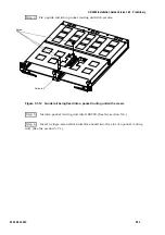
Insert the network interface board into the slot until it reaches the position
indicated in the figure below, and fold its levers to the indicated direction. (The network
interface board will be inserted into the slot completely.)
Figure 5.7-5
Network interface board being locked
*
NOTE: When inserting a network interface board into the slot, do it holding its levers so
that its connector part is fixed into its position correctly. When moving levers,
do it slowly without giving much pressure to them.
Step 3
Fasten the screws of the network interface board.
!
Caution: Use a driver when screwing up a packet routing unit, and make sure that it is
fixed into its position firmly.
Step 4
Attach the network interface cable to the network interface board.
(
As for the attachment of an interface cable, refer to the section 4.10 Connecting
Interface Cables to the GR4000.
)
5.7.2 Additional installation/replacement of double-size NIF
WARNING: The replacement of a network interface board should be done by a trained
engineer or a qualified maintenance person.
!
Caution: Do not touch the electronic components on the solder side of a network
interface board. To avoid damage, always store these components in approved
anti-static bags.
Lever
Lever
Содержание GR4000 Series
Страница 1: ...Hitachi Gigabit Router GR4000 Series Installation Guide Version 1 00 Preliminary ...
Страница 98: ...GR4000 Installation Guide Version 1 00 Preliminary 80 520 10 014 20X This page left intentionally blank ...
Страница 152: ...GR4000 Installation Guide Version 1 00 Preliminary 134 520 10 014 20X ...
Страница 164: ...GR4000 Installation Guide Version 1 00 Preliminary 146 520 10 014 20X This page left intentionally blank ...


