


40
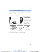
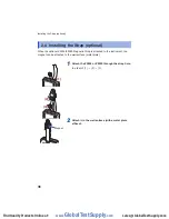
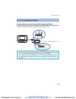
Connecting Cables
Using the CT9691-90, CT9692-90 or CT9693-90
The CT9691-90, CT9692-90, and CT9693-90 are each composed of the CT9691,
CT9692, or CT9693 Clamp Sensor and CT6590 Sensor Unit.
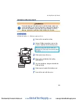
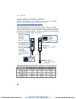
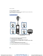
CT6590 Sensor Unit overview and parts names
The CT6590 Sensor Unit is a unit to connect the CT9691, CT9692, and CT9693
Clamp ON AC/DC Sensor to the measuring instrument. The clamp sensor measures
current and the instrument converts and outputs the voltage signal. After connecting
the sensor to the measuring instrument, correct any deviation in the output using the
zero adjustment knob before starting measurement.
2
RATING
LR 6
2
BAT TERY
POWER LED
Green lamp lit:
Power ON
Red lamp lit:
Low battery
Lamp off: Power OFF
AC adapter
connection
terminal
Sensor
connection
terminal
Connect the clamp
sensor.
Battery cover
Remove the screw and insert
batteries.
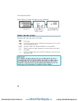
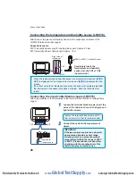
BNC connector
Connect the connector to
the LR8513.
Zero adjustment knob
Turn the knob to the left or
right to adjust the zero point
of the connection sensor
.
Selector switch
H: High range
L: Low range
OFF: Power OFF
The range level varies
depending on the clamp
sensor.
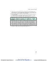
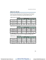
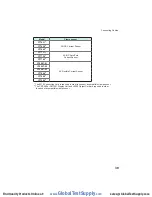
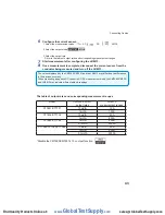
Output rate and range of the CT9691-90, CT9692-90, and CT9693-90 Sensor
CT9691 sensor
CT9692 sensor
CT9693 sensor
H
Range (f.s.)
100 A
200 A
2000 A
Output rate
1 mV/A
1 mV/A
0.1 mV/A
L
Range (f.s.)
10 A
20 A
200 A
Output rate
10 mV/A
10 mV/A
1 mV/A
Output (f.s.)
100 mV
200 mV
200 mV
www.
GlobalTestSupply
.com
Find Quality Products Online at:


