147
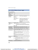
LR8512 Wireless Pulse Logger
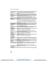
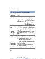
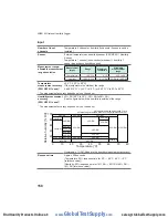
Input
Number of input
channels
2 channels
Input terminal
Mini jack
Applicable input
form
Non-voltage a-contact (normal open contact), open collector, or voltage
input
Maximum input
voltage
0 V to 50 V DC
Input resistance
1.1 M
Ω
±5%
Maximum rated
voltage between
input channels
Non-isolated (GND common)
Maximum rated
voltage to earth
30 V AC rms or 60 V DC (between each analog input channel and
chassis)
Anticipated transient overvoltage: 330 V
Detection level
Can be changed between 2 levels.
HIGH: 1.0 V or higher, LOW: 0 V to 0.5 V
HIGH: 4.0 V or higher, LOW: 0 V to 1.5 V
Chattering
prevention filter
The ON/OFF setting can be made at each channel.
Measurement
object
Pulse or logic input is exclusively set for each channel.
Measurement mode
Integrating (cumulative, instant)/Revolution/Logic (records 1/0 for each
recording interval)
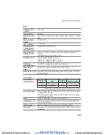
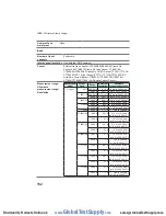
Pulse input
Measurement
range/resolution
Measurement
object
Range
Maximum
resolution
Measurement range
Integrating
1,000 mega pulses f.s.
1 pulse
0 to 1,000 mega pulses
Revolution
5,000/n [r/s] f.s.
1/n [r/s]
0 to 5,000/n [r/s]
n indicates the number of pulses per one revolution and is 1 to 1,000.
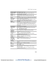
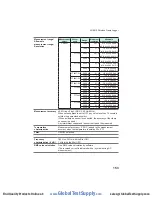
Pulse input cycle
200 µs or longer when the filter is set to OFF (must be 100 µs or longer
in H period and L period.)
100 ms or longer when the filter is set to ON (must be 50 ms or longer
in H period and L period.)
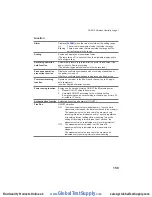
Slope
Rising or falling edge can be set for each channel.
Integrating count
Records an integrated count value from the start of measurement for
each recording interval.
Instant count
Records an instant count value for each recording interval.
Revolution
The number of input pulses is counted for a second and the revolution
is calculated.
www.
GlobalTestSupply
.com
Find Quality Products Online at:


