


Calibration
Kerf width correction
For the second ring exactly the same file can be used. Now that the angles corrections have been
enterred the kerf width can be accurately measured. Load the same cutting file as you used for the first
ring and select an initialisation point. Cut the two chamfers as before. Using a pair of calipers, measure
the width of the ring. The width at the inner and outer walls should now be the same, if this is not the
case check your angle corrections have been correctly entered in the settings (positive or negative).
If the ring is too narrow (smaller than 20 mm)
the value of the kerf width in the settings must
be increased by half the difference. The software
has not compensated enough. So if the width
is 18 mm, the difference is 2 mm, increase the
kerf width value by 1 mm. If the ring is too wide
(more than 20 mm) the value of the kerf width
must be decreased. The software has over
compensated. So if the width is 22 mm, the
difference is 2 mm, decrease the kerf width in the
settings by 1 mm.
Virtual Burner Height correction
When cutting a bevelled chamfer, the cutting head will move to the side to compensate for the angle so
that the inside wall of the pipe is on the cut line. The distance that the cutting head moves depends on
the angle of the bevel and the virtual burner height (see the VBH diagram earlier in this chapter). To
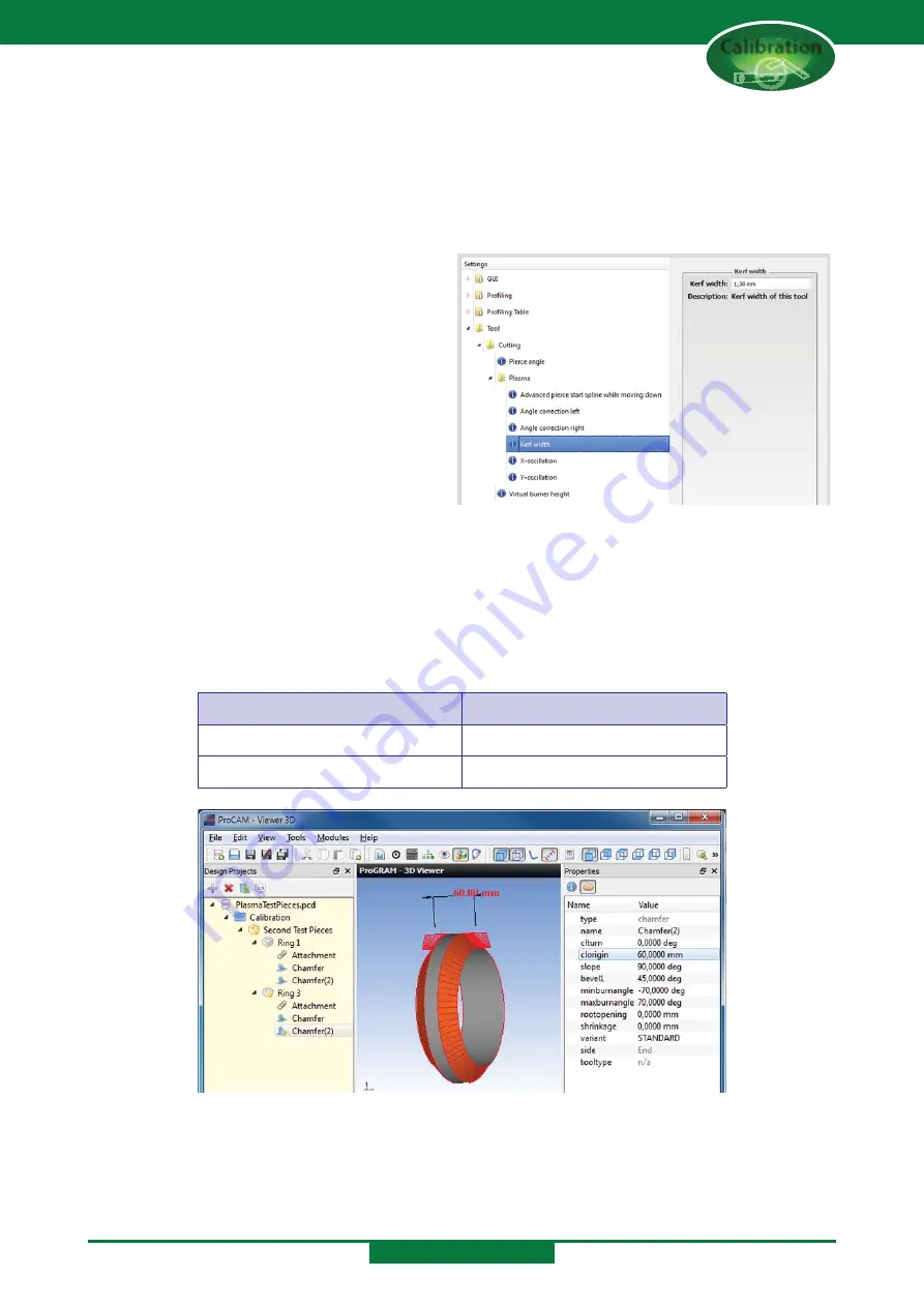
evaluate the offset you can now cut a third ring. Because this ring will have bevelled sides, the ring will
have to be wider than the first two. Program the third ring in exactly the same way as the first one but
with the following values changed:
Chamfer - start (will be cut first)
Chamfer (2) - End
clorigin = 0 mm
clorigin = 60 mm
bevel1 = 45°
bevel1 = 45°
Using a pair of calipers, measure the width of the ring at the inner wall. This should be 60 mm. If the
width is greater than 60 mm, the virtual burner height is too low and the value must be increased.
If the width is less than 60 mm, the virtual burner height is too high and the value must be decreased.
CALIBRATION
Содержание SPC 1000
Страница 71: ...Appendix A Maintenance and Grease Schedule Grease Schedule...
Страница 81: ...Appendix B Calibration and Cutting Test Pieces Calibration...
Страница 100: ...Appendix C Software Messages Notifications and Errors Software Messages i i i i i...
Страница 139: ...Appendix D Software Restore Software Restore...
Страница 154: ...Software Restore SOFTWARE RESTORE...
Страница 163: ...Appendix E Cutting Quality Cutting Quality...
Страница 166: ...Appendix F Terminology Terminology...
Страница 169: ...SPC Operators Manual Pipe Profiling Machines SPC 500 1200 PT HGG Profiling Equipment www hgg group com...