


Calibration
Cutting the second test pieces for plasma
In order to correct deviations caused by the factors mentioned in the previous section you should now
cut a series of rings from a pipe with the same (or similar) dimensions to the material from which your
parts are to be cut. Whenever you change material or change the consumables in your plasma torch it is
advisable to cut these pieces again. The size of the nozzle opening, the cutting current, the wall thickness
of the material and the plasma gases used can all have an effect on the width and shape of the plasma
beam.
Plasma angle correction
Open ProCAM by clicking on the icon at the top of the touchscreen. Create a new file in ProCAM.
Make sure the part has the exact dimensions of the pipe you are using to cut your rings. In the
MDI module, program a ‘Chamfer’ macro on the start and end sides. The value of the bevel should be 0°.
The ‘clorigin’ parameter (centreline origin) determines the length of the part, in this case the width of the
ring. Set this value to at least 20 mm on the end side in the MDI module. The default ‘Slope’ parameter
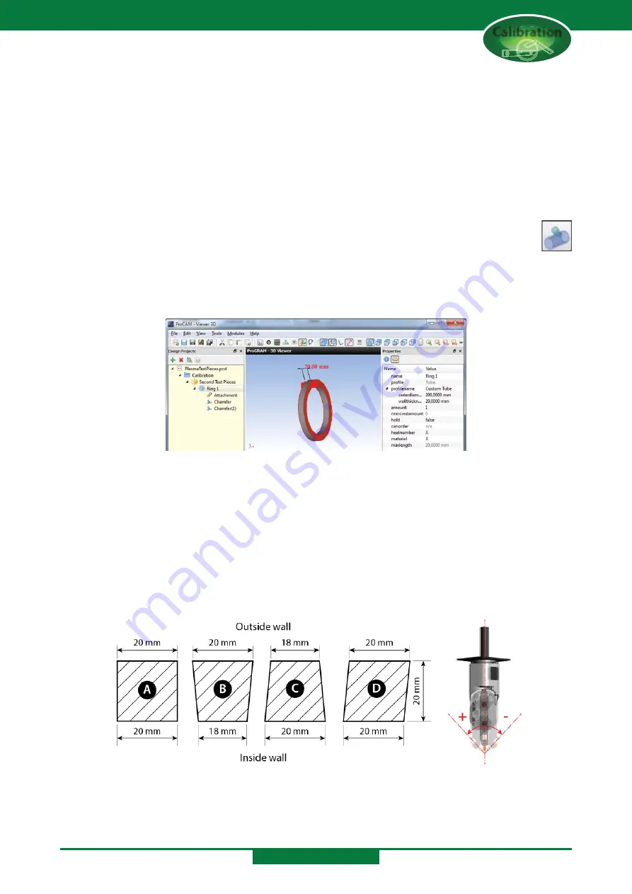
(for a perpendicular cut) is 90°. In ProCAM the part will look like the image below.
When the part has cooled, use a pair of calipers to measure the width of the ring at the outer wall and at
the inner wall at several places around the ring. The perfect ring should be 20 mm wide at all locations
on both the inner and outer walls. If there is a difference between the width of the inner and outer walls,
measure the angle and enter the angle in the settings. Because the pipe will rotate in opposite directions
for the two chamfers (see cutting direction) the angles on the left and right side of the ring may differ
so it is important that you know which side is which (for example mark the right side of the ring before
cutting the left side). In the settings enter the angle corrections for the left and right sides of the ring.
See the diagram below showing a section of the wall of the ring to determine whether the correction
should be positive or negative. If you have corrected the wrong way the in the next cut you will see that
the deviation is twice as bad!
A No corrections
B Angle correction right = positive. Angle correction left = negative.
C Angle correction right = negative. Angle correction left = positive.
D Angle correction right = negative. Angle correction left = negative.
CALIBRATION
Содержание SPC 1000
Страница 71: ...Appendix A Maintenance and Grease Schedule Grease Schedule...
Страница 81: ...Appendix B Calibration and Cutting Test Pieces Calibration...
Страница 100: ...Appendix C Software Messages Notifications and Errors Software Messages i i i i i...
Страница 139: ...Appendix D Software Restore Software Restore...
Страница 154: ...Software Restore SOFTWARE RESTORE...
Страница 163: ...Appendix E Cutting Quality Cutting Quality...
Страница 166: ...Appendix F Terminology Terminology...
Страница 169: ...SPC Operators Manual Pipe Profiling Machines SPC 500 1200 PT HGG Profiling Equipment www hgg group com...