17730-241
55
Component Replacement
AR2
™
40K • 46K
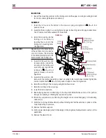
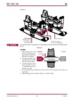
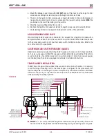
FIguRE 8‑30
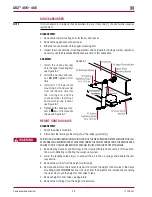
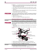
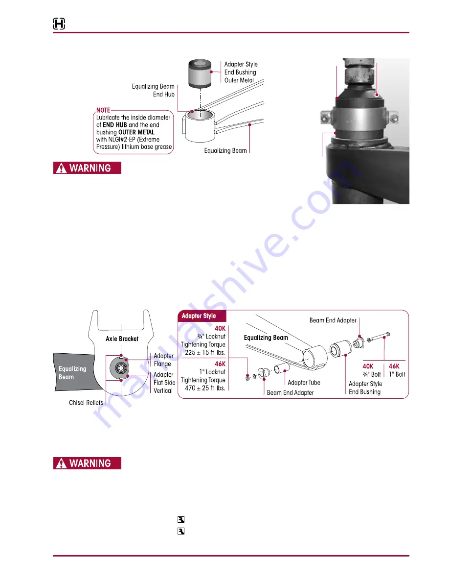
FIguRE 8‑31
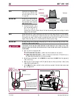
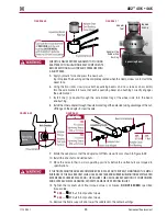
CHECK TO ENSURE PROPER ALIGNMENT OF TOOLING
ADAPTERS WITH EQUALIZING BEAM COMPONENTS
BEFORE APPLYING FULL HYDRAULIC PRESSURE WITH
A SHOP PRESS .
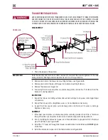
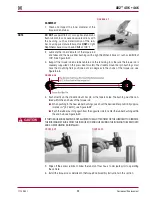
5 . Apply hydraulic force and press the new bush-
ing into place . The bushing will be completely seated when the clamp makes contact with the
beam face .
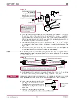
6 . Using the floor jacks, slowly raise both equalizing beams and cross tube as an assembly
into the axle brackets . Ensure that each equalizing beam end bushing correctly engages
the axle bracket .
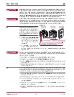
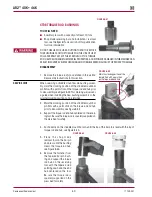
7 . Install one (1) adapter through the axle bracket leg at the wheel side, into the beam
end bushing .
8 . Install the other adapter through the axle bracket leg at the axle side, taking advantage of the cut-
off flange on the adapter to clear the axle .
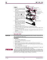
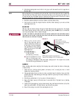
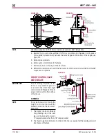
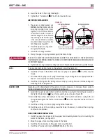
FIguRE 8‑32
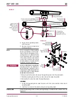
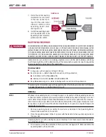
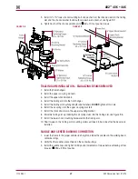
FIguRE 8‑33
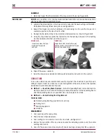
9 . Rotate the adapters so that the adapter cut-off flats are vertical as shown in Figure 8-32 .
10 . Install the end shaft and slotted nuts .
11 . Place the axles in their normal operating positions before the slotted nuts are torqued to
specifications .
IF THE TIGHTENING TORQUES RECOMMENDED BELOW ARE NOT PROPERLY MAINTAINED, THE METAL
SURFACES OF THE AXLE BRACKET LEGS, HOLES, ADAPTERS AND RUBBER BUSHING INNER METALS CAN
EXPERIENCE EXCESSIVE WEAR AND / OR FAILURE . THIS CAN CAUSE SEPARATION OF COMPONENTS
AND ADVERSE VEHICLE HANDLING, PROPERTY DAMAGE OR PERSONAL INjURY .
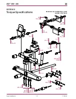
12 . Tighten the locknuts until final torque value is achieved,
dO NOT ExCEEd
specified
torque value
.
■
40K
— 225 ± 15 foot pounds torque
■
46K
— 470 ± 25 foot pounds torque
13 . Remove the frame supports and lower the saddle onto the center bushings .
Adapter
Tool
Clamp
Equalizing Beam
Adapter Style
Rubber End
Bushing
Tapered
End Up

