Component Replacement
54
17730-241
AR2
™
40K • 46K
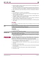
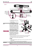
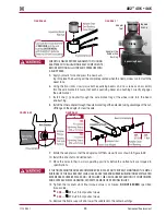
FIguRE 8‑27
FIguRE 28
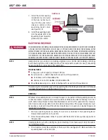
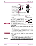
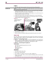
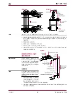
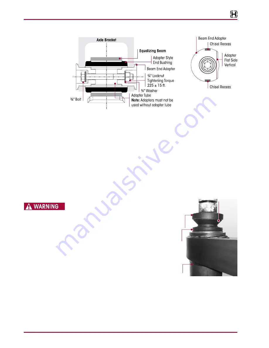
10 . The beam end adapters have two chisel recesses located in their flanges as shown in
Figure 8-28 .
11 . Locate the recess for the chisel, rotate the adapter if necessary . Place the air hammer / chisel
in the recess to rotate the adapter collar .
12 . If the beam end adapter does not turn, use a hammer to rap the outside of the axle bracket
legs around the adapter area and repeat air hammer chisel procedure until removed .
13 . Remove the beam end adapter from the other equalizing beam ends .
14 . Slowly lower the floor jacks and remove / pry the equalizing beams from the axle brackets .
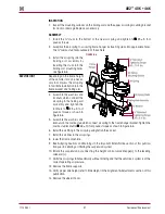
15 . Remove the end bushing adapter tube (if equipped), see Figure 8-27 .
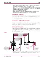
16 . Remove the floor jacks from under the equalizing beams .
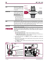
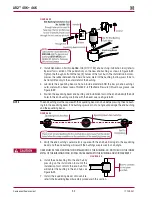
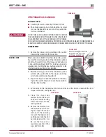
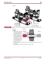
17 . Position the equalizing beam in the shop press and align the end bushing removal /
replacement adapter tool with the
tapered end down
on top of the rubber end bushing,
see Figure 8-29 .
FIguRE 8‑29
CHECK TO ENSURE PROPER ALIGNMENT OF TOOLING
ADAPTERS WITH EQUALIZING BEAM COMPONENTS
BEFORE APPLYING FULL HYDRAULIC PRESSURE WITH
A SHOP PRESS .
18 . Apply hydraulic force and remove the
old bushing .
19 . Inspect the axle bracket legs per the Beam End
Axle Brackets, Physical Inspection for Adapter
Style bushings in the Preventive Maintenance
section of this publication .
INSTALLATION
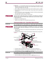
1 . Clean the equalizing beam bushing bore with a
cylinder ball hone or emery paper of any debris .
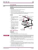
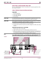
2 . Lubricate the equalizing beam bore and the equalizing beam center bushing outer metal
sleeve with an NLGI#2 – EP (Extreme Pressure) grease, see Figure 8-30 .
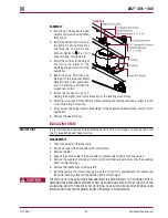
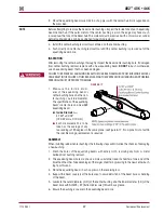
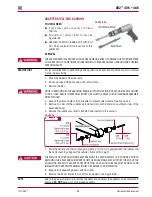
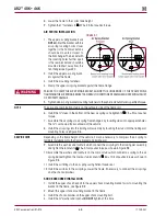
3 . Position the end bushing removal / replacement adapter with the
tapered end up
onto the
clamp, see Figure 8-31 .
4 . Use a wrench to tighten the installing clamp tool on the rubber bushing and the end bushing
replacement adapter as shown in Figure 8-31 .
End Bushing
Replacement
Adapter
Receiver
Equalizing Beam
End
Bushing
Tapered
End Down

