


17730-241
23
Preventive Maintenance
AR2
™
40K • 46K
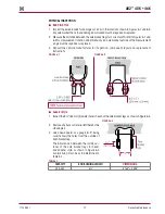
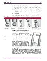
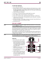
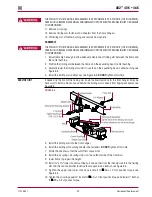
FIguRE 6‑12
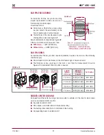
Both types of rods may have torque
rod bushings designated “straddle
mount” or “tapered stud” as shown
in Figure 6-12 . Both types can be
replaced by pressing out the worn
bushing and installing a new genu-
ine Hendrickson bushing . For proper
replacement instructions, refer to the
Component Replacement section in
this publication .
It is important to check the torque rod fasteners for proper torque values, refer to the Torque
Specifications section in this publication .
NOTE
Hendrickson recommends Grade 8 bolts, hardened flat washer and Grade C locknuts be used for
all straddle mount torque rods .
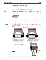
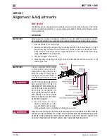
SAddLE CONNECTION
Visually inspect for any signs of movement or looseness . Ensure:
■
Each saddle is centered on each equalizing beam center bushing
■
The center bushing inner metal is full seated to the saddle
■
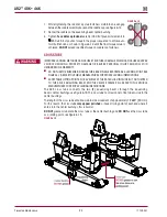
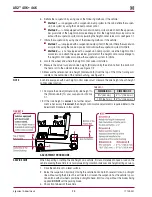
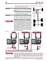
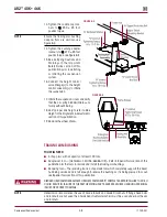
The saddle cap fasteners are tightened to the proper torque, see Figure 6-13 . Saddle cap
fasteners have a phosphate oil coating
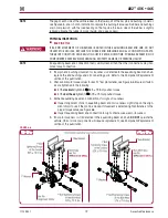
THE TRAILING ARM ASSEMBLIES ARE ATTACHED TO THE CENTER BUSHINGS OF EACH EQUALIZING BEAM
WITH TWO (2) SADDLE CAPS . EACH SADDLE CAP USES TWO (2) STUDS TO CLAMP THE CENTER BUSHING
INNER METAL TO THE SADDLE . THE SADDLE CAPS MUST BE INSTALLED AND TIGHTEN SO THAT THERE IS
AN EVEN GAP BETWEEN THE SADDLE CAPS AND THE BASE OF THE TRAILING ARM ASSEMBLY AS SHOWN
IN FIGURE 6-13 . IF THEY ARE NOT INSTALLED PROPERLY, THE TRAILING ARM ASSEMBLIES COULD BECOME
DEFORMED, RESULTING IN BENT BOLTS OR ASSEMBLY DAMAGED .
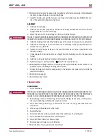
LOOSE OR OVER TORQUED FASTENERS CAN CAUSE COMPONENT DAMAGE, ADVERSE VEHICLE
HANDLING, PROPERTY DAMAGE, OR SEVERE PERSONAL INjURY . MAINTAIN CORRECT TORQUE VALUES
AT ALL TIMES . CHECK TORQUE VALUES ON A REGULAR INSPECTION INTERVAL .
FIguRE 6‑13