


17730-241
53
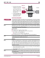
Component Replacement
AR2
™
40K • 46K
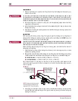
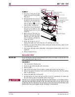
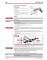
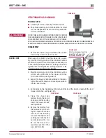
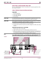
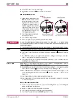
AdApTER STYLE ENd BuSHINg
FIguRE 8‑25
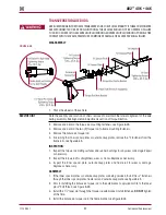
YOu wILL NEEd
■
A shop press with a capacity of at least
100 tons
■
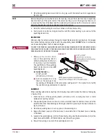
Air hammer / chisel / Bent chisel, see
Figure 8-25
■
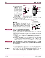
Hendrickson Part No . 66086-102 (OTC Part
No . 1764), see Special Tools section of this
publication
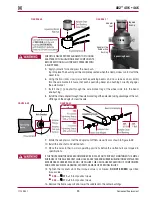
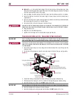
REMOVAL
THE ADAPTER REMOVAL PROCESS CAN CAUSE DAMAGE . REUSE OF DAMAGED OR WORN ADAPTERS
COULD RESULT IN A COMPONENT FAILURE LEADING TO ADVERSE VEHICLE HANDLING AND POSSIBLE
PERSONAL INjURY .
SERVICE HINT
It is recommended that a penetrating oil be applied to all beam end connections prior to removal
to aide in disassembly .
1 . Chock the wheels of the steer axle .
2 . Raise and support the drive axles with safety stands .
3 . Remove the tires .
PRIOR TO REMOVING BOTH EQUALIZING BEAMS, SUPPORT THE PINION OF EACH DRIVE AXLE . FAILURE
TO DO SO CAN RESULT IN PERSONAL INjURY OR ALLOW THE AXLES TO SHIFT MAKING REASSEMBLY
MORE DIFFICULT .
4 . Support the pinion angle of the drive axles to prevent axle movement during service .
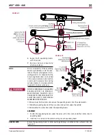
5 . Remove and discard the saddle cap fasteners from both inboard and outboard sides of the
equalizing beam .
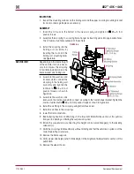
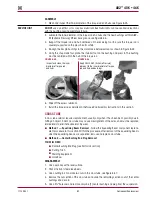
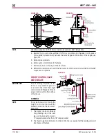
6 . Remove the saddle caps, refer to Saddle Cap Assembly in this section .
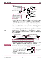
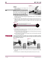
FIguRE 26
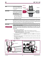
7 . Raise the vehicle’s frame just enough to create a ½" (13 mm) gap between the saddles and
the center bushings . Support the vehicle’s frame at this height .
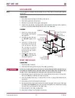
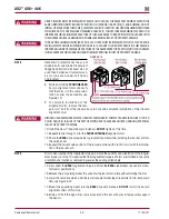
THE WEIGHT OF THE EQUALIZING BEAM ASSEMBLY IS APPROXIMATELY 155 POUNDS . PRIOR TO
REMOVING THE BEAM END FASTENERS FROM THE EQUALIZING BEAM, SUPPORT THE END OF THE
EQUALIZING BEAM TO PREVENT FROM DROPPING . CARE SHOULD BE TAKEN AT REMOVAL AND
INSTALLATION TO PREVENT PERSONAL INjURY OR DAMAGE TO COMPONENTS .
8 . Support both equalizing beams with floor jacks .
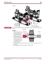
9 . Remove the beam end bolt or shaft (as equipped), see Figure 8-26 .
NOTE
Due to the process necessary to remove the beam end adapters, the adapter can be subjected to
damage .
dO NOT
reuse worn or damaged adapters .


