17730-241
31
Alignment & Adjustments
AR2
™
40K • 46K
6 . Ensure all drive axle tires are at the same size .
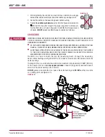
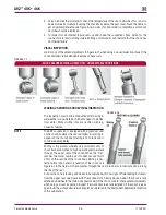
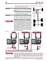
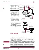
7 . Securely clamp a six-foot piece of
STRAIGHT
bar stock or angle iron across the lower frame
flange as shown in Figure 7-5 . Select a location for the bar stock or angle iron as far forward
of the drive axle as possible where components will not interfere .
8 . Accurately square the bar stock or angle iron to the frame using a carpenter’s square .
9 . Using a measuring tape, measure from the straight edge to the forward face of the front drive
axle arms on both sides of the vehicle as shown in Figure 7-5, dimensions
A
and
B
.
10 . Calculate the difference between measurements
A
and
B
.
a . If the
front
drive axle is within vehicle manufacturer’s specifications, proceed to check the
rear drive axle (Step 11) .
b . If alignment of the
front
drive axle
IS NOT
within the vehicle manufacturer’s specifications,
then the alignment of this axle
MuST
be corrected
BEFORE
measuring the rear drive axle
alignment (Step 11) .
c . If the suspension is equipped with bar pin end bushings, correct the alignment of this axle
by following the bar pin alignment instructions in this section .
NOTE
Since the remaining drive axle will be aligned relative to the front drive axle, it is essential that the
front drive axle is aligned within the vehicle manufacturer’s specifications prior to the alignment
of the remaining drive axle .
11 . Using a trammel bar, measure the distance from the spindle center of the
front
drive axle to
the spindle center of the rear drive axle on both sides of the vehicle; see Figure 7-5,
C
and
D
.
12 . Calculate the difference between measurements
C
and
D
.
a . If the measurements are within the vehicle manufacturer’s specifications, then the
rear
drive axle alignment is acceptable .
b . If alignment of the
rear
drive axle
IS NOT
within the vehicle manufacturer’s specifications,
then the alignment of this axle
MuST
be corrected .
c . If the suspension is equipped with bar pin end bushings, correct the alignment of this axle
by following the Bar Pin with Shims Alignment instructions in this section .
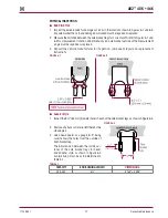
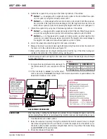
FIguRE 7‑6
13 . Recheck measurements to confirm adjustments . Repeat
Steps 10 through 12 until the correct alignment is
achieved .
14 . After all drive axles are aligned, check the pinion angle
of each drive, refer to the Axle Pinon Angle in this section .
LATERAL ALIgNMENT
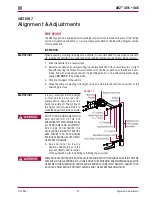
1 . Use a work bay with a level, flat surface .
2 . Drive the vehicle slowly, straight ahead . Try to slacken or
loosen the suspension as the vehicle is positioned . End
with all wheels positioned straight ahead . Try to roll to
a stop without the brakes being used .
dO NOT
set the
parking brake .
3 . Chock the front wheels of the vehicle .
4 . Verify and maintain the air system at full operating
pressure .
5 . Verify the vehicle is at the correct ride height . Correct as
necessary . Refer to Ride Height in this section .

