


17730-241
47
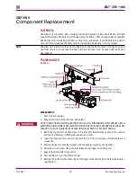
Component Replacement
AR2
™
40K • 46K
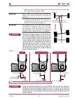
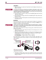
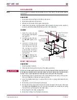
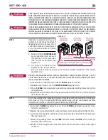
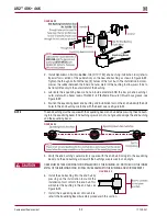
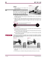
19 . Partially install the
REAR INBOARd
bar pin alignment shim and verify that the shim is in the
same orientation as prior to disassembly, see Figure 8-10 .
20 . To complete installation of the alignment shim, remove the temporary ¾" bolt from the
inboard bar pin hole and complete installation of the inboard alignment shim .
21 . Install new 1" inboard bar pin fasteners .
dO NOT
tighten at this time .
22 . Repeat steps 19 through 21 for the
REAR OuTBOARd
bar pin alignment shim .
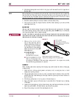
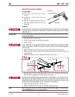
NOTE
Prior to assembly of the longitudinal torque rod, note the quantity and orientation of the longitudi-
nal torque rod shims . It is required that the longitudinal torque rod shims are installed in the same
orientation and location as removed to preserve the existing alignment .
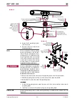
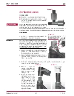
23 . Install the longitudinal torque rod and any longitudinal torque rod shims in the same orientation
as prior to disassembly . Tighten the fasteners to the vehicle manufacturer’s specifications .
24 . Re-apply rear parking brake .
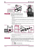
NOTE
Prior to assembly of the rear bar pin end bushing fasteners, ensure that all the bar pin shims are
installed in the same orientation as prior to disassembly .
DISCARD USED FASTENERS . ALWAYS USE NEW FASTENERS TO COMPLETE A REPAIR . FAILURE TO DO SO
COULD RESULT IN FAILURE OF THE PART OR MATING PARTS, ADVERSE VEHICLE HANDLING, PERSONAL
INjURY, OR PROPERTY DAMAGE .
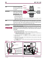
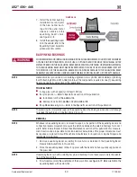
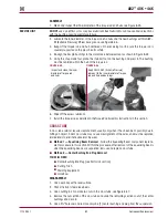
25 . Tighten the bar pin end fasteners to:
■
At the
locknuts
tighten to 525 ± 75 foot pounds torque
■
At the
bolt head
tighten to 575 ± 75 foot pounds torque
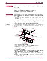
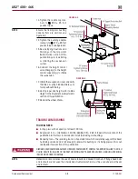
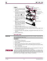
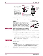
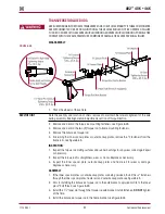
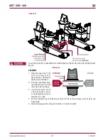
FIguRE 8‑14
THE TRAILING ARM ASSEMBLIES ARE ATTACHED TO THE CENTER BUSHINGS OF EACH EQUALIZING BEAM
WITH TWO (2) SADDLE CAPS . EACH SADDLE CAP USES TWO (2) STUDS TO CLAMP THE CENTER BUSHING
INNER METAL TO THE SADDLE . THE SADDLE CAPS MUST BE INSTALLED AND TIGHTEN SO THAT THERE IS
AN EVEN GAP BETWEEN THE SADDLE CAPS AND THE BASE OF THE TRAILING ARM ASSEMBLY AS SHOWN
IN FIGURE 8-14 . IF THEY ARE NOT INSTALLED PROPERLY, THE TRAILING ARM ASSEMBLIES COULD BECOME
DEFORMED, RESULTING IN BENT BOLTS OR ASSEMBLY DAMAGED .
NOTE
Hendrickson recommends the use of Grade 8 bolts and Grade C locknuts . If flange head bolts and lock-
nuts are not used then hardened structural washers must be used under bolt heads and locknuts .
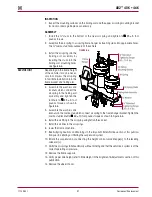
26 . Remove the frame supports and lower the frame of the vehicle being careful to engage the
trailing arm assembly on the equalizing beam’s center bushings .
27 . Center the trailing arm assembly on the equalizing beam center bushing, see Figure 8-15 .