background image

Revision C  •  10/07

H

A

R

R

I

S


C

O

R

P

O

R

A T

I

O

N

4-7

4 RMX

digital Server

INITIAL CONFIGURATION  PROCEDURE

This procedure requires that both CM and

VMCC be installed on the setup computer; that

the RMX

digital console is installed and powered

up using the factory IP setting of 192.168.100.22;

and that the setup computer and the RMX

digital

are networked together.

1 Start Community Monitor

Click the desktop icon (

) on the setup com-

puter to start Community Monitor. This adds a

miniature icon to the taskbar tray. Right-click

on the tray icon to select Show Monitor Dis-

play. An example is shown below:

The new console should be shown in the dis-

play with an IP address of 192.168.100. 22. If

the console is not shown, then CM may be lis-

tening to the wrong Ethernet port on the setup

computer.

To change which port CM uses, click 

Options,

then select 

Setup. If 192.168.100.11 is not

shown in the Community Local IP address win-

dow, click the window’s down arrow, select that

address, then close and restart CM.

Once the new RMX

digital console is shown

in the CM display, the setup computer is prop-

erly communicating with the new console.

2 Start VMCC (desktop icon:


)

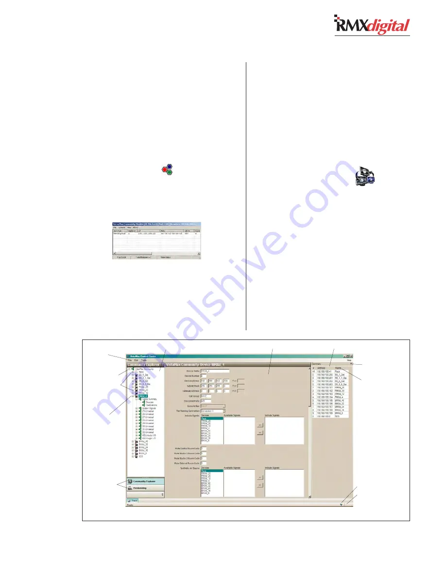
The first time VMCC starts up, no community

is displayed. Click the 

Tools menu and select

New Community to start setting up a new com-

munity. Use the illustration below to identify

the VMCC user interface features.

The Editing pane, in the middle of the pro-

gram window, allows global parameters for the

VistaMax community to be set when the com-

munity name is highlighted in the Community

Explorer pane along the left side. These param-

eters include naming the new community and

changing the administrator address (which uses

the setup computer’s IP address: 192.168.

Community Monitor display

Community Explorer Pane

Editing Pane

Community Summary Pane

Hide Summary 
Pane button

To Reorder Summary List,
click #, Address, or Name

Saved Status Flag
Saving Database Icon

Community Name

Menu items
(File, Edit, Tools)

Community Devices  
R = RMXdigital
B=BMXdigital
E= Edge device

Active Device
(parameters shown in 
the editing pane)

Left Pane Activity 

Selection Tabs

VMCC, graphical interface features

Содержание RMXDIGITAL

Страница 1: ...Broadcast Console Operations Technical Manual PRE75 53 PRE75 53 PRE75 53 PRE75 53 PRE75 53 Revision C 1 12 10 Broadcast Communications Division www broadcast harris com...

Страница 2: ...Revision C 10 07 H A R R I S C O R P O R A T I O N ii...

Страница 3: ...n 3 9 Telco Codec Operation 3 10 4 RMXDIGITAL SERVER RMXd File Structure 4 1 RMXd Server Configuration 4 5 Session Files 4 17 Session Macro Files 4 20 Software Updates 4 27 Settings Recovery 4 27 5 SE...

Страница 4: ...d above conforms to the above Directive s and Standard s EN55103 1 Studio Environment EN55022 Class A Magnetic Field Emissions EN55103 2 Studio Environment EN61000 4 2 EN61000 4 3 EN61000 4 4 EN61000...

Страница 5: ...essor essories ies ies ies ies Donotplacethisproductonanunstable cart stand tripod bracket or table The product may fall causingseriousinjurytoachildoradultandserious damage to the product Any mounti...

Страница 6: ...ceive a revision to this document from Harris replace the old manual pages with the new ones and discard the old pages Replace this page with the new Manual Revisions page Revision Affected pages Comm...

Страница 7: ...p cutout Framesizes with 12 20 or 28 con trol strips are available The console can operate in a stand alone capacity or for maximum flex ibility and usability be integrated with aVistaMax Audio Manage...

Страница 8: ...ging to a production room at night Since session files can change any number of console settings dayparting the console is as easy as selecting the desired session file and pressing Take once the sess...

Страница 9: ...in this section for the power supply KSU and DSP cards and for the optional 8 Input Expansion cards Universal Dual Fader Panels Each Dual Fader panel has two sets of channel strip controls with these...

Страница 10: ...nal fifteen sources The selected source button lights to indicate its selection while blanking the selected name display When a source is selected using the source selector the name is shown in the te...

Страница 11: ...nnections support runs up to 2 km An optical Link RMXd8 HL PRE99 1910 2 is also available On the consoles the KSU card plugs into the motherboard behind the Monitor Control panel and the two adjacent...

Страница 12: ...mat AES 3 S PDIF input only AES 3 Input Output Compliance 24 bit sample rate conversion Digital Reference Crystal internal or VistaMax slave external at 48 kHz 100 ppm Internal Sample Rate 48 kHz Outp...

Страница 13: ...tputs 86 dB 20 Hz to 20 kHz Console Power Requirements RMXd8 HL 48 watts RMXd 12 99 watts RMXd 20 141 watts RMXd 28 186 watts Measured at 115 230VAC 12 50 60 Hz Power Supply Voltage Console power 48 V...

Страница 14: ...ths from the DATE OF SHIP MENT from Harris A copy of the domestic USA product warranty policy dated July 1 2007 is presented on the fol lowing two pages To view or download the current Harris Broad ca...

Страница 15: ...al support as a substitute for training of customer s personnel then such technical support will be subject to additional charges at Harris then prevailing unit rate for such services 2 Before shippin...

Страница 16: ...the Licensed Programs which is found by Harris inspection not to be in substantial compliance with its specifications If Harris is unable to provide a corrected copy of the Licensed Programs within a...

Страница 17: ...panel a KSU card and the DSP cards installed with the optional items ordered Universal Dual Fader Panels Blank Panels 8 Input Expansion Cards 2 RU rackmount 48 volt power supply Installation and tool...

Страница 18: ...one KSU card with DSP for the buses four input channels and four special purpose phantom channels Each DSP card adds the DSP for another eight input channels e g RMXd 4 has no DSP card RMXd 12 has on...

Страница 19: ...ual Fader panel NOTE Either or both channel strips on a Dual Fader panel can be set as a Telco input channel but only six total channels can be set as the six unique Telco channels on the console The...

Страница 20: ...s set as Telco chan nels have lightedTalkback buttons If desired the Talkback button cover can be replaced by a clear cover and a label to identify each Telco channel There are no other adjustments or...

Страница 21: ...is play top right on the reflective display Press Fast to increment time by minutes at a time Press Slow to increment time by seconds at a time Press and hold Hold to freeze the clock to synch it to a...

Страница 22: ...23456789012345678901234567890 123456789012345678901234567890 123456789012345678901234567890 123456789012345678901234567890 123456789012345678901234567890 Switch Table DSW2 switch 1 and 2 set the level...

Страница 23: ...ettings ON OFF 1 Average Peak Average only 2 2 sec Peak Hold No Peak Hold 3 Blue LED turn on level 4 Blue LED turn on level 5 NetWave RMXdigital 6 Display mirrored direct view Blue Peak LEDs turn on a...

Страница 24: ...console and the peripheral ends when all system compo nents share a common ground potential and are using isolated ground AC outlets tied individually back to the main technical ground If isolated gr...

Страница 25: ...day use To install the backup batteries 1 Open the card access cover 2 Install the three batteries into the battery clip located behind the KSU card on the frame Observe the polarity as marked on the...

Страница 26: ...ver all cable jacket cut ends to insulate the shield wiring Logic control cables are fabricated in a similar manner to the audio wiring Strip the jacket insu lation back 1 38 10 mm sleeve the cut end...

Страница 27: ...MOD IV receptacle con tact in one crimp To use the ratcheting crimp tool 1 Insert the contact into the contact holder with the barrel openings up Typically the middle holder is used for 20 24 AWG wir...

Страница 28: ...moval Tool included in the 76 1401 tool kit is required Insert the tool s tip into the locking tab slot and press the locking tab down while lightly pulling on the wire to remove the contact from the...

Страница 29: ...n the init mac file see Chapter 4 for how to change the sample rates on these outputs When the console is used in a stand alone ap plication the console cannot be locked to an ex ternal time reference...

Страница 30: ...onnects to CD1 CD1 s logic would connect to the B Logic I O connector Likewise audio inputs C and D are associated with the C and D Logic the RMXdigital is then automatically synchro nized to theVista...

Страница 31: ...LSE 6 TALLY PULSE COMMON 7 5 VOLT LOGIC SUPPLY 8 COUGH READY 9 ON 10 5 VOLT LOGIC SUPPLY 11 ON TALLY START PULSE 12 5 VOLT LOGIC SUPPLY 14 9 8 5 12 4 Control Room Warning Relay Control Room Warning Re...

Страница 32: ...s 14 pin connector has the same connections as the control room connector except they re for a talk studio or voice room There are two isolated relay contacts pins 4 and 5 for controlling a warn ing l...

Страница 33: ...e connector so its buttons can control a channel strip while tally outputs control the but ton tallies in sync with the channel strip buttons The init mac or the active session file sets the binding f...

Страница 34: ...LEDs connect to pins 5 7 and 11 with pin 1 supplying a ground connection The On Tally output pin 11 drives the LEDs in the On button and the OffTally pin 5 drives the LEDs in the Off button The other...

Страница 35: ...Switch Talkback Switch 1 2 3 4 5 6 7 8 1 5 11 7 3 9 8 2 6 12 4 10 Logic Ground Off Tally On Tally 5 VDC Supply Off Switch On Switch Cough Switch Talk Switch Tally Common 5 VDC supply Enable Logic Inp...

Страница 36: ...s that follow on pages 2 19 to 2 23 FROM 48 VOLT UNIVERSAL POWER SUPPLIES PRIMARY REDUNDANT 1 4 48 VDC 2 SHIELD 3 6 48 RETURN 5 N C 6 5 4 3 2 1 CAT 5 CABLE TO STUDIO MONITOR PANEL TECHNICAL GROUND MET...

Страница 37: ...nd control logic for an external location See page 2 22 for signal details LOGIC I O CONT B B B B B C C C C C D D D D D Assignable Logic I O connections associated with their matching audio input anal...

Страница 38: ...e is active Output is a N O dry contact type that is typically used to drive a mute indicator or to mute talk and cue speakers Connects to Relays Common pin 10 while dim is active Output is a N O dry...

Страница 39: ...y the channel strip logic When pulled low turns the channel off turning on the Off Tally output and generating a Stop Pulse when Line logic is active This is a momentary connection that is latched by...

Страница 40: ...nnects to Relays Common pin 3 while receiving a Talk to External command Output is a N O dry contact type that is typically used to drive an indicator or to switch a signal to a talk speaker To enable...

Страница 41: ...Connectors x8 FOR AN ANAL FOR AN ANAL FOR AN ANAL FOR AN ANAL FOR AN ANALOG INPUT OG INPUT OG INPUT OG INPUT OG INPUT Set the matching numbered DIP switch toward the board operator to select analog Co...

Страница 42: ...COM NORMAL DATA SYSTEM MASTER PRE99 1363 1 COPPER FACETS EXT AES REFERENCE INPUT VALID EXT REF 0 1 2 3 4 5 3 2 1 _ CONTROLLER INACTIVE CTRL COM NORMAL DATA PRE99 1360 SYSTEM RESET TEST INTERFACE CONT...

Страница 43: ...Y On tally output N O contact 12 5 5 5 5 5 V V V V VOL OL OL OL OLT L T L T L T L T LOGIC SUPPL OGIC SUPPL OGIC SUPPL OGIC SUPPL OGIC SUPPLY Y Y Y Y 5 volt source for switch tallies Notes VDC is betw...

Страница 44: ...ULSE COMMON OMMON OMMON OMMON OMMON Start Stop Pulse common C contact 7 5 VOLT LOGIC SUPPLY 5 volt source 8 READ READ READ READ READY INPUT Y INPUT Y INPUT Y INPUT Y INPUT Remote Ready switch input ac...

Страница 45: ...7 5 VOLT LOGIC SUPPLY 5 volt source 8 READ READ READ READ READY INPUT Y INPUT Y INPUT Y INPUT Y INPUT Remote Ready switch input active low 9 ON INPUT ON INPUT ON INPUT ON INPUT ON INPUT Remote On swi...

Страница 46: ...1 clear in sert sheet to create custom lens labels The 80 1961 sheet with diecut inserts for both small and large lenses can be laser or inkjet printed One 80 1961 sheet is included in the 76 1400 kit...

Страница 47: ...m other RMXdigital consoles or VistaMax or En voy cardframes A Quick Guide to using Universal Dual Fader panels is on pages 3 2 and 3 3 MONITOR CONTROL PANEL This standard panel is installed near the...

Страница 48: ...ed off FCN FCN FCN FCN FCN Function button Press and hold to access special channel strip features It is not active at this time F F F F Fader ader ader ader ader 100mm channel level control with dB i...

Страница 49: ...d R lit the inputs are summed to mono and then fed to both left and right bus outputs P P P P PAN B AN B AN B AN B AN BAL AL AL AL AL When lit the pan balance control is active When unlit the pan bala...

Страница 50: ...akers and operator headphones the right column has the studio monitoring controls monitor source selectors and level controls for studio speakers Each column s functions are separately detailed over t...

Страница 51: ...tton settings input source names and other information as a new session saved locally in the console The new session name is the current session name plus a numerical suffix Note Note Note Note Note S...

Страница 52: ...ck back Adjusts the output level of the dedicated Talk to Control Room TLK CR output and the talkback level into the Cue speaker when Talk to Cue is set during console setup CONTROL ROOM MONITOR SOURC...

Страница 53: ...udio M tudio Monit onit onit onit onitor S or S or S or S or Sour our our our ourc c c c ce N e N e N e N e Name D ame D ame D ame D ame Displa ispla ispla ispla isplay y y y y Shows the selected moni...

Страница 54: ...e bargraph 20 dBFS setting A detailed bargraph meter is shown below Each bar segment from 0 to 30 represents a 1 dB level change between bars From 30 to 57 each bar represents a 3 dB difference in lev...

Страница 55: ...or a digital signal from a satellite receiver aTelco interface a remote traf fic feed a processed mic a digital delivery system output an ISDN output any audio signal needed in the facility that is pl...

Страница 56: ...X There are two mono foldback signals alternately termed IFB for Interruptible Foldback or mix minus signals associated with each Telco chan nel One output adds talkback audio over the mix minus feed...

Страница 57: ...Telco channel has a different bus priority order for selecting which is the foldback feed While the Channel is On or Off the primary foldback source is Offline If it is not assigned then the program b...

Страница 58: ...Record Telco Channel LEFT CHANNEL RIGHT CHANNEL NOT RECORDED All Telco channels which are assigned TO RECORD by the session file All channels assigned to the Base Mix bus including those Telco module...

Страница 59: ...ing system as BMXdigital consoles and VistaMax frames only one setup computer running VMCC is required to maintain all of the files on all of the VistaMax devices that are networked together in theVis...

Страница 60: ...MCC It loads automatically each time the SBC starts up It sets default routes default logic set tings and logic I O bindings to audio sources monitor and meter selection button assignments mute codes...

Страница 61: ...o 84 and 91 to 94 are the 8 Input Expansion cards and the KSU s audio and logic connections The numbers are the hex equivalent of session file channel ID numbers ROUTERS INI This file also maintained...

Страница 62: ...the console s KSU card outputs As shown a dual selector panel VM SSD is configured so that the left buttons identi fied as Button_1_1 thru 6 are hot source keys to control the source for destination 1...

Страница 63: ...Radix entry a pe riod in the example above and the four character Community Name as defined in the VMCC Sig nal Summary RMXd Server Configuration Several software programs must be installed on the se...

Страница 64: ...installation and setup information CONFIGURATION PREREQUISITES The following items are required before the RMXdigital Server can be configured for a spe cificVistaMax system A setup computer running W...

Страница 65: ...address then close and restart CM Once the new RMXdigital console is shown in the CM display the setup computer is prop erly communicating with the new console 2 Start VMCC desktop icon The first tim...

Страница 66: ...r Select the 192 168 100 11 card click OK and reinspect the community Verify there s a check mark under the Inspect heading for the RMXd console doubleclick the box to add the check mark Click the Ins...

Страница 67: ...lick Save When Normal or Force Download was selected VMCC opens a Device Specific Distribution window while checking that it can communicate with the various com munity devices This window also lists...

Страница 68: ...x frames 192 168 100 41 up to 49 VistaMax Intercoms 192 168 100 50 up to 100 Consoles RMXd or BMXd 192 168 100 101 up to 199 VistaMax Edge Devices 192 168 100 200 up to 299 to avoid conflicts when add...

Страница 69: ...take effect Use Community Monitor to verify the new console was setup cor rectly CM will list the console name device num ber and its IP address CONSOLE SIGNAL SETUP Having configured the nqx ini fil...

Страница 70: ...edit them as required If too many characters are entered or if an illegal char acter is entered a red exclamation point and error warning box will be shown so the error can be corrected Signal Format...

Страница 71: ...ital delivery system with a Ready command output to indicate sta tus of the device The Off lamp on the channel strip that this signal is routed to will then be controlled by the incoming Ready logic c...

Страница 72: ...gnals list Re peat for the other devices To remove any sources from the Include List highlight the signals then click the double left arrow key Select Monitor Meter Include Lists Sources There are thr...

Страница 73: ...o PGM 1 if there are no selections made To use automatic monitor switching Real Air must be used as the control room monitor source It is the default signal assigned to the top button on the monitor s...

Страница 74: ...z or 44 1 kHz The other digital outputs have a fixed 48 kHz sample rate output Chain to a Session File After the operating system completes loading at console start up the init macfile is loaded In th...

Страница 75: ...me with a numbered suffix Since session names are limited to 10 alpha numeric characters the original session name will be truncated as required as in undefine01 ses to add the numbered suffix EDITING...

Страница 76: ...ll channel button set tings but rotary knob and fader settings are not saved as part of the session file 3 Press the Save button to save the channel set tings A new session file named undefine01 has b...

Страница 77: ...l copy of undefine01 ses 2 Edit the file as required Note See Session and Init mac Files start ing on the next page for more information on editing session files 3 Save the file with a new name such a...

Страница 78: ...nel strips installed plus the four phantom channels which are numbered 29 30 31 and 32 Since similar channel ID numbers are likewise assigned to BMXdigital console components and to the audio and logi...

Страница 79: ...following a semicolon Any text proceeded by a are comments used to clarify the session file BUTTON SETTING SECTIONS Every channel strip button has their own sec tion in the session file where the butt...

Страница 80: ...ault PanBalance Sets whether the channel s pan balance control is on or off TelcoAuto Sets whether the Auto Foldback feature is on or off for each Telco channel TelcoRecord Sets whether the Telco chan...

Страница 81: ...auto matically rewritten by the RMXdigital Server at each save so it should not be edited The table entries are in hex with Map_0 being a reserved position listed as 00 for no channel de tected Map_1...

Страница 82: ...is taken In previous examples one source has been shown being routed to one destination but any one source can be routed to any number of desti nations by adding separate Take command lines from that...

Страница 83: ...ually changed to override the default console settings for a par ticular daypart or application The init mac file is maintained and edited using VMCC so none of these entries are manu ally edited in t...

Страница 84: ...r a start pulse or 124 for stop pulse c defines which timeslots are used by the logic commands Typically the odd num bered timeslots starting with slot 1 are used in order This gets automatically assi...

Страница 85: ...fter the RMXdigital con sole is power cycled The RMXdigital must be taken off air during this procedure To update the RMXdigital software 1 Configure theTFTP Server to point to the folder on the CD RO...

Страница 86: ...nt 3 Power cycle the RMXdigital console As the RMXdigital Server starts up HyperTerminal will show multiple screens of information Look for the USER entry a shown below USER username password Use the...

Страница 87: ...the cor rect parts are ordered have the Harris part num bers available when ordering For a list of parts see page 5 2 Panels cards and assemblies may have lead times exceeding two weeks so order acco...

Страница 88: ...ole Display 76 1403 Monitor Control panel removable lens kit 76 1404 Universal Dual Fader panel removable lens kit 80 1752 Lens covers 10 character display and LEDs 80 1846 Card cage slot blank panel...

Страница 89: ...eset and Start buttons together When ControlTest mode is active the following is shown in the source name display Move each rotary control and fader and observe their encoder pulse output count in hex...

Страница 90: ......

Страница 91: ...eached and unplugged from the bottom of the panel NOTE If you need to replace one of the assem blies please contact Harris Technical Services Department for service or replacement parts Installing Con...

Страница 92: ...ning the fader parts Always use a clean dry swab to dry off the con ductive plastic tracks after cleaning If the fader rails are noticeably dirty wipe them off using a dry cotton swab then lubricate t...

Страница 93: ...oard connection Check the charging circuit and motherboard connection by removing one battery and then measuring the voltage should be about 4 5 VDC on the bat tery terminals while the console is powe...

Страница 94: ...or channel strips 1 and 2 it plugs into the first Universal Dual Fader panel The next cable is for channel strips 3 and 4 the next Dual Fader panel and so on up to the two used for the Monitor Control...

Страница 95: ...es not affect console settings and signals It only causes the SBC to reestablish its Ethernet connec tion with the network which typically requires one to two minutes During this time no new routes ca...

Страница 96: ...rom KSU I O cable J11 To I O 2 J12 To I O 3 J13 To Universal Dual Fader panel 1 J14 To Universal Dual Fader panel 2 J15 To FX Panel J16 To Monitor Control Panel J17 To Studio Selector Panel J18 From 4...

Страница 97: ...t your Harris sales representative for de tails Accessory Panels Turret accessory panels maintain the console s look and feel while providing remote control for important studio functions RMXdigital a...

Страница 98: ...UDIO MONITOR SELECTOR FADER PANELS The studio monitor s source selection can be controlled in the studio by using a Studio Monitor Selector Panel 99 1190 with the RMXdigital The panel connects to the...

Страница 99: ...n puts can come from the Control Room and or Stu dio Host and Guest headphone outputs Headphone level is digitally controlled when the 99 1214 series headphone panels are used Head phone panels are av...

Страница 100: ...CR8 CR7 S1 S2 S4 S3 GNDD GNDD GNDD These items are not populated on the 99 1197 Panel J1 TO ASSIGNABLE LOGIC CONNECTOR Mic Remote Control Panel Connections J2 TO FROM GROUP MIC CONTROLLER J1 TO FROM C...

Страница 101: ...C Sessions and Macros VMCC FILE MAINTENANCE The VMCC application icon not only simplifies device configuration it also allows one stop file maintenance for everyVistaMax commu nity member any console...

Страница 102: ...to and to send out UDP commands When a device requires TCP IP to be used in stead then the nqx ini file must be modified so that TCP IP commands are used If only one device requires this setting whic...

Страница 103: ...console cards in the Explorer pane each input card starts with the card ID number assigned to that card It is only on the RMXd 28 that these numbers correspond to their physical positions on the conso...

Страница 104: ...s the Group Publish file These signal names consist of the Discipline Sort Char acter the Discipline Prefix and the Community Name e g PROD MD1 The devices in the other Call Sign groups then receive t...

Страница 105: ...ssigned to remote mic control panel buttons In cluded in this list are several signals that are only available on the BMXdigital console The signals that should not be selected on RMXdigital include T...

Страница 106: ...aVMCC en tered device only works if the inspected device and the existing VMCC device match exactly in regards to framesize and the types of cards in stalled and the card slot positions If the two dev...

Страница 107: ...re these common formatting rules all command text is held within sections each section begins with a Section Name header can be up to 32 characters each KeyValue uses a separate line within the sectio...

Страница 108: ...try for each channel strip in the console These types of headings were detailed in chapter 4 Telco Record and Telco Monitor These twoTelco section headings get automati cally created when a session f...

Страница 109: ...network signal and the A Analog out put send to network signal RouterCommand_1 take_1 337 151 Hybrid In Fader 12 take_2 161 241 MM 1 KSU Analog A The previous macro is selected on fader 12 If this Tel...

Страница 110: ...e on the local device Macro 4 bayonne is loaded on device 6 Here is the ses sion file command syntax for assigning macros to a router channel Router_x Macro_n Filename d x is the channel ID of the rou...

Страница 111: ...anel e g no Dual Fader panel is installed in that slot means there are two more phantom channels available for each blank panel in the console Each RMXdigital also includes several phan tom buses that...

Страница 112: ...ort of power cycling the console is to run a session file that has this section force_off channel_13 1 channel_14 0 channel_15 0 channel_16 0 which forces the first phantom channel off to re move it f...

Страница 113: ...lumn so intercom panels can be added to create the group Highlight the names of the intercom panels to include in the highlighted call group then click the double right arrow so the names appear in th...

Страница 114: ...277 return logic to CD 2 Take_3 1 339 cancel logic VoxPro Take_4 1 343 cancel logic InstRply This macro routes CD 2 to fader 15 and routes the channel 15 logic to the CD player while also routing sile...

Страница 115: ...rvicing 5 7 Bargraph Meters Description 3 8 DIP Switch Settings 2 7 Troubleshooting 5 6 Basic Peripheral Device Logic Example 2 28 C Cabinet Cutout 2 1 Cabinet Plates 6 1 Cabling andWiring 2 10 Audio...

Страница 116: ...2 27 ESE Cable Connection 6 3 Master Clock 2 5 Event Timer DIP switch Settings 2 6 On Console Display 3 8 Troubleshooting 5 6 Ethernet Connection 2 21 F Facet Connections 2 21 Fader Panels 6 2 Fader...

Страница 117: ...ini File 4 5 nqx ini Settings 4 10 O Operation 3 1 Outputs Audio Logic KSU Card 2 21 8 Input Expansion Card 2 25 P Parts Ordering 5 1 Part Lists 5 2 Peripheral Devices Basic Peripheral Example 2 28 C...

Страница 118: ...4 Setting the Clock 2 5 Software Updates 4 27 S PDIF Signals 2 13 Specifications 1 6 Studio section Monitor Control panel Operation Quick Guide 3 7 Overview 1 4 Studio Control Turret 6 2 Page numbers...

Отзывы: