14.09.2020
71 / 156
VARMAX -
Installation, Use and Maintenance
B. NECESSARY ADJUSTMENT ACCESSORIES
Quantity
Appliance
reference
Order No.
Extension module kit (delivered with a
QAD 36 network sensor)
3
AVS 75
059751
External sensor kit
1
QAC 34
059260
Ambient sensor kit
(diagram VX102)
3
QAA 75
040954
DHW sensor kit
(diagram VX112)
1
QAZ 36
059261
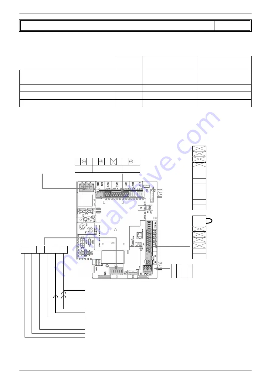
C. CUSTOMER ELECTRICAL CONNECTION
L
N L3
N
L3 L
N
QX2
QX3
QX1
BX2
Gnd
BX3
Gnd
B3
Gnd
B9
Gnd
H1
Gnd
H5
Gnd
G+ CL- CL+ G+ CL- CL+
Mains supply 230
VAC 50 Hz
}
}
}
}
External sensor B9
Alarm
relay
Diagram VX112:
DHW sensor B3
}
}
Diagram VX102:
Ambient sensor QAA 75 for
heating circuit No. 1
Diagram VX102:
Ambient sensor QAA 75 for
heating circuit No. 2
Diagram VX102:
Ambient sensor QAA 75 for
heating circuit No. 3
Diagram VX112
only
Diagrams: VX102 / VX112
page 2 / 6
Gnd UX3 Gnd UX2
If an external management
system (e.g. PLC) or a
command pump (boiler,
heating and/or DHW circuit)
is connected, refer to § 9.4 for
the specific configuration).
Содержание VARMAX 120
Страница 11: ...14 09 2020 11 156 VARMAX Installation Use and Maintenance ...
Страница 44: ...44 156 00BNO9168 I U0606551 VARMAX Installation Use and Maintenance figure 33 Electrical wiring diagram ...
Страница 125: ...14 09 2020 125 156 VARMAX Installation Use and Maintenance ...
Страница 155: ...14 09 2020 155 156 VARMAX Installation Use and Maintenance ...


