Page
88
SmartFOAM
REMOTE ON/OFF SWITCH OPERATION
The remote ON/OFF switch is used to activate the Hale
SmartFOAM system from the driver compartment or a loca-
tion other than the SmartFOAM controller display. The
switch activates and deactivates the Hale SmartFOAM sys-
tem. It does not permit adjustment of the injection rate.
The SmartFOAM system will use the injection rate of the
preset set for “remote activation” (see the
SETTING PRE-
SETS
section). If no preset has the “remote activation” ena-
bled then the injection rate used will be the current set rate
on the SmartFOAM controller.
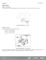
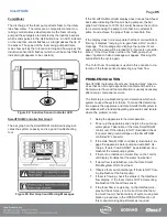
Refer to
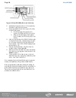
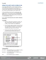
Figure 50: Remote Activation Switch Installation
To operate:
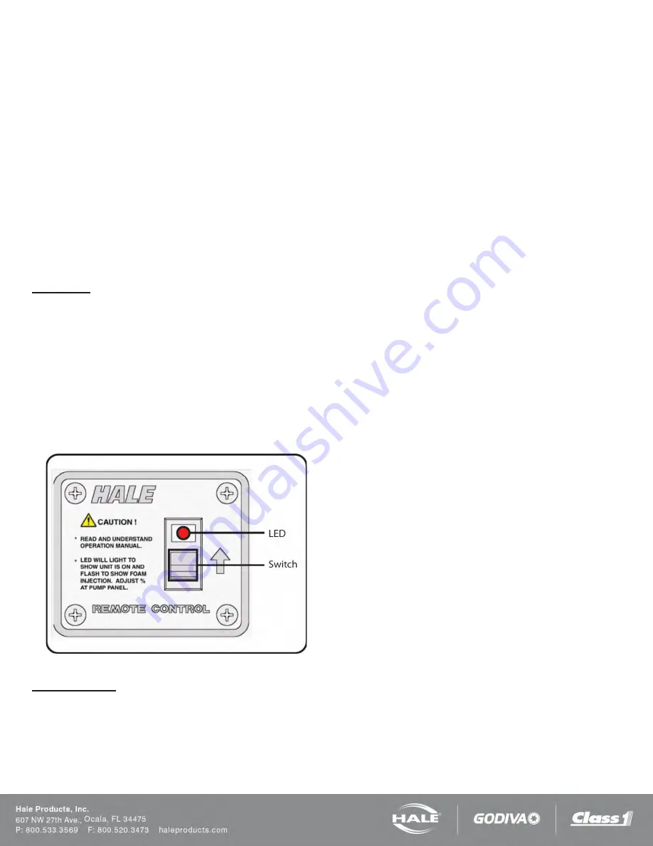
1. Press the switch down and release to activate. The
LED turns ON SOLID, indicating the Hale Smart-
FOAM is in the STANDBY mode (
2. When the foam capable discharge nozzle is opened
the LED BLINKS, indicating foam concentrate is be-
ing injected. When the nozzle is closed, the LED
stops blinking and again turns ON SOLID.
3. Pressing the switch again deactivates the Hale
SmartFOAM system and the LED turns OFF.
Figure 75: Remote Activation Switch
LED indications:
ON SOLID - The SmartFOAM system is enabled but waiting
for water flow before injecting foam.
BLINKING - The SmartFOAM system is enabled and cur-
rently injecting foam.
OFF
- The SmartFOAM system is disabled.
Содержание MiniCAFS 2.1A
Страница 3: ...Page 2 SmartFOAM NOTES...
Страница 12: ...Page 11 SmartFOAM HALE FOAM PUMP DIMENSIONS Figure 1 1 7 and 2 1 Foam Pump Installation Envelope Dimensions...
Страница 15: ...Page 14 SmartFOAM Figure 5 Converter Installation Envelope Dimensions Located Remote for 6 5 12VDC Systems...
Страница 16: ...Page 15 SmartFOAM SYSTEM DIAGRAM Figure 6 Typical Hale SmartFOAM 2 1A and 1 7AHP System...
Страница 17: ...Page 16 SmartFOAM Figure 7 SmartFOAM 3 3 5 0 6 5 Single Tank System with In line Strainer...
Страница 18: ...Page 17 SmartFOAM Figure 8 SmartFOAM 3 3 5 0 6 5 Single Tank withMSTandIn lineStrainer...
Страница 19: ...Page 18 SmartFOAM Figure 9 SmartFOAM 3 3 5 0 6 5 Single Tank withMSTandFSSeriesStrainer...
Страница 20: ...Page 19 SmartFOAM Figure 10 SmartFOAM 3 3 5 0 6 5 Dual Tank withMDTIIandIn lineStrainers...
Страница 21: ...Page 20 SmartFOAM Figure 11 SmartFOAM 3 3 5 0 6 5 Dual Tank withMDTIIandFSSeriesStrainer...
Страница 22: ...Page 21 SmartFOAM Figure 12 SmartFOAM 3 3 5 0 6 5 Dual Tank withADTandIn lineStrainers...
Страница 23: ...Page 22 SmartFOAM Figure 13 SmartFOAM 3 3 5 0 6 5 Dual Tank withADTandFSSeries Strainers...
Страница 24: ...Page 23 SmartFOAM Figure 14 SmartFOAM Dual Pump 1 Single Tank with Valve Options and In Line Strainers...
Страница 25: ...Page 24 SmartFOAM Figure 15 SmartFOAM Dual Pump 1 Single Tank System with MST and FS Series Strainers...
Страница 26: ...Page 25 SmartFOAM Figure 16 SmartFOAM Dual Pump 1 Dual Tank System with MDT II and FS Series Strainers...
Страница 27: ...Page 26 SmartFOAM Figure 17 SmartFOAM Dual Pump 2 Single Tank System with valve options and In Line Strainers...
Страница 28: ...Page 27 SmartFOAM Figure 18 SmartFOAM Dual Pump 2 Single Tank System with MST and FS Series Strainers...
Страница 29: ...Page 28 SmartFOAM Figure 19 SmartFOAM Dual Pump 2 Dual Tank System with MDT II and FS Series Strainers...
Страница 48: ...Page 47 SmartFOAM Figure 28 Typical 4 Inch Check Valve Installation Midship Pump...
Страница 59: ...Page 58 SmartFOAM Figure 43 ADT Option Air Hose Connections Part 2...
Страница 68: ...Page 67 SmartFOAM Figure 55 Top Mount Low Level Sensor Assembly...
Страница 77: ...Page 76 SmartFOAM NOTES...
Страница 90: ...89 Page 89 SmartFOAM NOTES...

