

Page
69
SmartFOAM
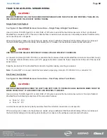
FOAM TANK LOW LEVEL SENSOR WIRING
CAUTION!
WHEN EXTENDING THE LOW TANK SENSOR WIRES MAKE SURE THE SPLICES ARE PROPERLY SEALED US-
ING AN ADHESIVE FILLED HEAT SHRINK TUBING.
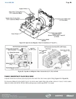
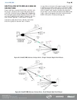
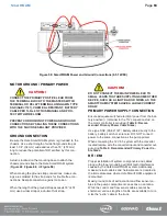
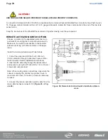
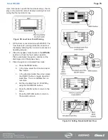
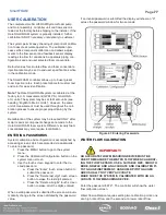
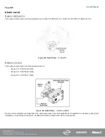
Single Foam Tank System
See
Figure 45: SmartFOAM Harness Connections – Single Pump & Single Tank Shown
Use a minimum 16 AWG type SXL or GXL (SAE J1128) wire to extend the low tank sensor wire to the 2-pin Packard
WeatherPack connector C10 of the main cable harness. Low tank level sensors are not polarity sensitive therefore termi-
nal connections are not specific.
When splicing wires make sure the splices are sealed using an adhesive filled heat shrink tubing. Where two wires exit
the heat shrink tubing pinch the tubing while heating the it to make sure the adhesive seals around both wires.
CAUTION!
USE THE SILICONE SEALER PROVIDED TO INSULATE AND PREVENT CORROSION.
A connector kit (Hale p/n: 546-1780-00-0) is available that contains a Packard WeatherPack 2-contact shroud half, two (2)
14-16 gauge male terminals and two (2) 14-16 gauge cable seals. Assemble these components to the end of the low tank
sensor wires.
Snap the two halves of the WeatherPack connector together making sure they are sealed.
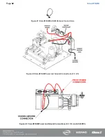
Note: If a Hale MST is not used, install the tank select jumper plug, Hale p/n: 513-0320-23-0, to connector C8.
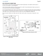
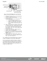
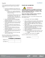
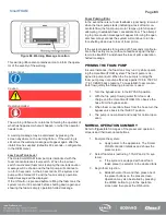
Dual Foam Tank System
See
Figure 46: SmartFOAM Harness Connections – Dual Pump & Dual Tank Shown
CAUTION!
BEFORE RUNNING WIRES FROM THE LOW TANK SWITCHES TO THE MAIN CABLE HARNESS MAKE SURE THE
WIRES FROM TANK “A” ARE IDENTIFIED AND PROPERLY LABELED.
Use a minimum 16 AWG type SXL or GXL (SAE J1128) wire to extend the low tank sensor wires to the 2-pin Packard
WeatherPack the following connectors of the main cable harness:
❑
Tank “A” - C10
❑
Tank “B” - C11
Low tank level sensors are not polarity sensitive therefore terminal connections are not specific.
When splicing wires make sure the splices are sealed using an adhesive filled heat shrink tubing. Where two wires exit
the heat shrink tubing pinch the tubing while heating it to make sure the adhesive seals around both wires.
Содержание MiniCAFS 2.1A
Страница 3: ...Page 2 SmartFOAM NOTES...
Страница 12: ...Page 11 SmartFOAM HALE FOAM PUMP DIMENSIONS Figure 1 1 7 and 2 1 Foam Pump Installation Envelope Dimensions...
Страница 15: ...Page 14 SmartFOAM Figure 5 Converter Installation Envelope Dimensions Located Remote for 6 5 12VDC Systems...
Страница 16: ...Page 15 SmartFOAM SYSTEM DIAGRAM Figure 6 Typical Hale SmartFOAM 2 1A and 1 7AHP System...
Страница 17: ...Page 16 SmartFOAM Figure 7 SmartFOAM 3 3 5 0 6 5 Single Tank System with In line Strainer...
Страница 18: ...Page 17 SmartFOAM Figure 8 SmartFOAM 3 3 5 0 6 5 Single Tank withMSTandIn lineStrainer...
Страница 19: ...Page 18 SmartFOAM Figure 9 SmartFOAM 3 3 5 0 6 5 Single Tank withMSTandFSSeriesStrainer...
Страница 20: ...Page 19 SmartFOAM Figure 10 SmartFOAM 3 3 5 0 6 5 Dual Tank withMDTIIandIn lineStrainers...
Страница 21: ...Page 20 SmartFOAM Figure 11 SmartFOAM 3 3 5 0 6 5 Dual Tank withMDTIIandFSSeriesStrainer...
Страница 22: ...Page 21 SmartFOAM Figure 12 SmartFOAM 3 3 5 0 6 5 Dual Tank withADTandIn lineStrainers...
Страница 23: ...Page 22 SmartFOAM Figure 13 SmartFOAM 3 3 5 0 6 5 Dual Tank withADTandFSSeries Strainers...
Страница 24: ...Page 23 SmartFOAM Figure 14 SmartFOAM Dual Pump 1 Single Tank with Valve Options and In Line Strainers...
Страница 25: ...Page 24 SmartFOAM Figure 15 SmartFOAM Dual Pump 1 Single Tank System with MST and FS Series Strainers...
Страница 26: ...Page 25 SmartFOAM Figure 16 SmartFOAM Dual Pump 1 Dual Tank System with MDT II and FS Series Strainers...
Страница 27: ...Page 26 SmartFOAM Figure 17 SmartFOAM Dual Pump 2 Single Tank System with valve options and In Line Strainers...
Страница 28: ...Page 27 SmartFOAM Figure 18 SmartFOAM Dual Pump 2 Single Tank System with MST and FS Series Strainers...
Страница 29: ...Page 28 SmartFOAM Figure 19 SmartFOAM Dual Pump 2 Dual Tank System with MDT II and FS Series Strainers...
Страница 48: ...Page 47 SmartFOAM Figure 28 Typical 4 Inch Check Valve Installation Midship Pump...
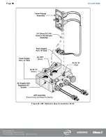
Страница 59: ...Page 58 SmartFOAM Figure 43 ADT Option Air Hose Connections Part 2...
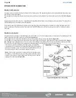
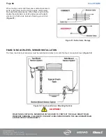
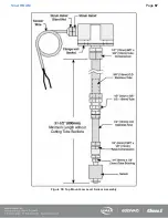
Страница 68: ...Page 67 SmartFOAM Figure 55 Top Mount Low Level Sensor Assembly...
Страница 77: ...Page 76 SmartFOAM NOTES...
Страница 90: ...89 Page 89 SmartFOAM NOTES...


