


Page
1
SmartFOAM
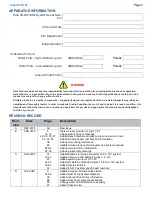
APPARATUS INFORMATION
Hale SmartFOAM System Serial Num-
ber
In Service Date
Fire Department
Engine Number
Calibration Factors:
Water Flow – high calibration point
Water flow
Pulses
Water Flow – low calibration point
Water flow
Pulses
Class A Foam Factor
NOTICE!
Hale Products does not assume responsibility for product failure resulting from improper maintenance or operation.
Hale Products is responsible only to the limits stated in the product warranty. Product specifications contained in this
manual are subject to change without notice.
All Hale products are quality components -- ruggedly designed, accurately machined, precision inspected, carefully as-
sembled and thoroughly tested. In order to maintain the high quality of your unit, and to keep it in a ready condition, it is
important to follow the instructions on care and operation. Proper use and good preventive maintenance will lengthen
the life of your unit.
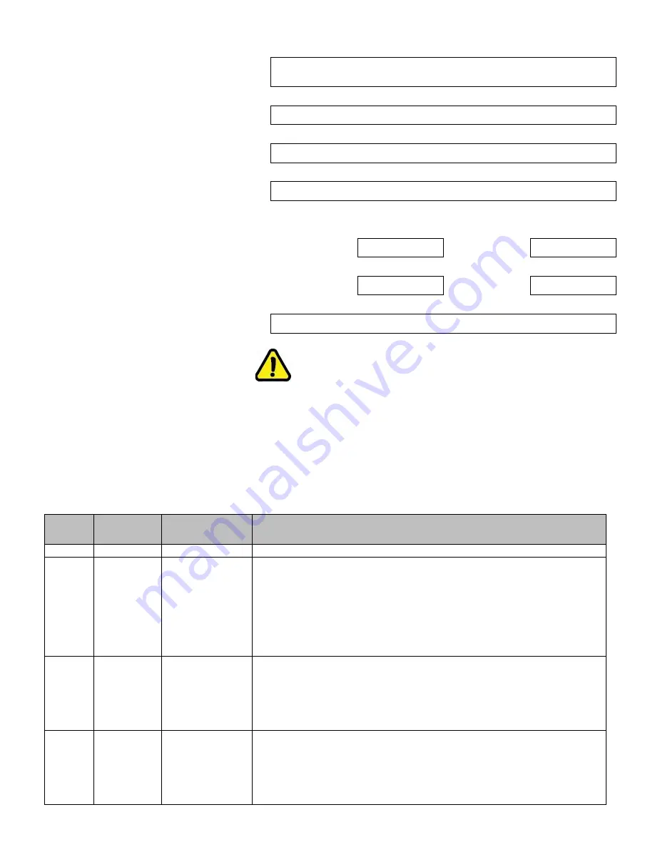
REVISION RECORD
Revi-
sion
Date
Page
Description
A
DEC 2015
All
New Issue
B
FEB 2018
6
12, 13
22, 34, 35, 47
23, 53, 54
36
82
83-84
87, 90
State all foam models not just 1.7/2.1
Add new Motor Driver drawings
Add pictures of piston and gear pump w/ new motor driver
Add new harness part numbers and information
Add new mounting information
Updated closed loop control diagram and system overview
Add new motor driver information
Add new Assembly drawings
C
JUN 2020
10
12-14
23
34-35
56-57
93
Adjusted tables to include converter on 6.5-12V system
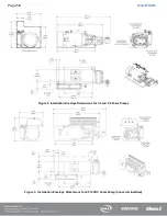
Updated Figure 2 and added Figures 3, 4, & 5
Added system picture for 6.5-12V
Adjusted Table 6 and added Figure 14 for 6.5-12V system
Added Figures 43 & 44
Added 6.5-12V system specific part numbers
D
JUL 2020
9
23-28
39
86
90
97
Updated maximum flow solution table
Added Dual Pump System diagrams
Added relevant Dual Pump information
Added Dual Pump system descriptions
Change water flow calibration to annually
Added Check Valve
Содержание MiniCAFS 2.1A
Страница 3: ...Page 2 SmartFOAM NOTES...
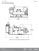
Страница 12: ...Page 11 SmartFOAM HALE FOAM PUMP DIMENSIONS Figure 1 1 7 and 2 1 Foam Pump Installation Envelope Dimensions...
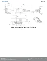
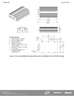
Страница 15: ...Page 14 SmartFOAM Figure 5 Converter Installation Envelope Dimensions Located Remote for 6 5 12VDC Systems...
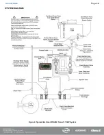
Страница 16: ...Page 15 SmartFOAM SYSTEM DIAGRAM Figure 6 Typical Hale SmartFOAM 2 1A and 1 7AHP System...
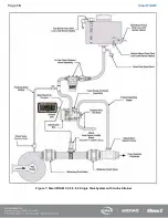
Страница 17: ...Page 16 SmartFOAM Figure 7 SmartFOAM 3 3 5 0 6 5 Single Tank System with In line Strainer...
Страница 18: ...Page 17 SmartFOAM Figure 8 SmartFOAM 3 3 5 0 6 5 Single Tank withMSTandIn lineStrainer...
Страница 19: ...Page 18 SmartFOAM Figure 9 SmartFOAM 3 3 5 0 6 5 Single Tank withMSTandFSSeriesStrainer...
Страница 20: ...Page 19 SmartFOAM Figure 10 SmartFOAM 3 3 5 0 6 5 Dual Tank withMDTIIandIn lineStrainers...
Страница 21: ...Page 20 SmartFOAM Figure 11 SmartFOAM 3 3 5 0 6 5 Dual Tank withMDTIIandFSSeriesStrainer...
Страница 22: ...Page 21 SmartFOAM Figure 12 SmartFOAM 3 3 5 0 6 5 Dual Tank withADTandIn lineStrainers...
Страница 23: ...Page 22 SmartFOAM Figure 13 SmartFOAM 3 3 5 0 6 5 Dual Tank withADTandFSSeries Strainers...
Страница 24: ...Page 23 SmartFOAM Figure 14 SmartFOAM Dual Pump 1 Single Tank with Valve Options and In Line Strainers...
Страница 25: ...Page 24 SmartFOAM Figure 15 SmartFOAM Dual Pump 1 Single Tank System with MST and FS Series Strainers...
Страница 26: ...Page 25 SmartFOAM Figure 16 SmartFOAM Dual Pump 1 Dual Tank System with MDT II and FS Series Strainers...
Страница 27: ...Page 26 SmartFOAM Figure 17 SmartFOAM Dual Pump 2 Single Tank System with valve options and In Line Strainers...
Страница 28: ...Page 27 SmartFOAM Figure 18 SmartFOAM Dual Pump 2 Single Tank System with MST and FS Series Strainers...
Страница 29: ...Page 28 SmartFOAM Figure 19 SmartFOAM Dual Pump 2 Dual Tank System with MDT II and FS Series Strainers...
Страница 48: ...Page 47 SmartFOAM Figure 28 Typical 4 Inch Check Valve Installation Midship Pump...
Страница 59: ...Page 58 SmartFOAM Figure 43 ADT Option Air Hose Connections Part 2...
Страница 68: ...Page 67 SmartFOAM Figure 55 Top Mount Low Level Sensor Assembly...
Страница 77: ...Page 76 SmartFOAM NOTES...
Страница 90: ...89 Page 89 SmartFOAM NOTES...


