


87
Page
87
SmartFOAM
concentrates deteriorate rapidly, and residue cannot be left
in the lines.
Note: Approved Class “A” foam concentrates do not deteri-
orate rapidly like Class “B” concentrates. As long as an ap-
proved Class “A” foam concentrate is used and the system
is operated within 10-12 weeks no flushing is required.
When Class “B” foam concentrate is used, always FLUSH
the system, then switch back to Class “A” (Figure 69 and
Figure 74).
1. Energize the apparatus and establish water flow
through a foam capable discharge. Set the fire pump
for a LOW discharge pressure, 50 to 75 PSI (3.4 to
5.2 BAR).
2. Energize the Hale SmartFOAM by pressing the ON
button, allowing foam solution to discharge.
Note: When the Hale ADT, MDTII or MST is in the
FLUSH position the Hale SmartFOAM foam injection
system runs for about twenty (20) second.
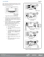
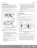
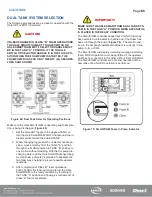
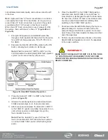
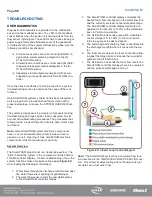
Figure 74: Hale MST Selector Operation
3. Place the Hale ADT, MDT II or MST to the FLUSH
position (
4. Observe the discharge hose and allow Hale Smart-
FOAM and discharge to run for several seconds.
5. After several seconds place the Hale ADT or MDT II
to the TANK “A” position and allow the system to run
until all foam solution is discharged through the
foam capable hose line.
Note: When the Hale MST is used for Class “B”
foam concentrates DO NOT allow the foam pump to
run in the FOAM TANK position after flushing foam
pump.
6. Place the Hale MST to the FOAM TANK position
and allow Hale SmartFOAM to run until Class “A”
foam solution is discharged through the foam capa-
ble hose line. If Class “B” foam concentrate is used,
shut down Hale SmartFOAM immediately after
switching to the FOAM TANK position.
7. Shut down Hale SmartFOAM allowing the foam ca-
pable discharge to continue to flush out the fire
pump discharge manifold as required. Once clear
water flows, close foam capable discharge and shut
down the apparatus.
8. Perform required maintenance checks on the Hale
SmartFOAM and apparatus to return the apparatus
to the ready condition.
IMPORTANT!
MAKE SURE THE HALE ADT OR MDT II IS IN THE TANK
“A” POSITION AND THE HALE MST IS IN THE FOAM
TANK POSITION WHEN APPARATUS IS PLACED IN THE
READY CONDITION.
Содержание MiniCAFS 2.1A
Страница 3: ...Page 2 SmartFOAM NOTES...
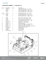
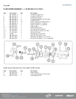
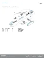
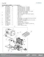
Страница 12: ...Page 11 SmartFOAM HALE FOAM PUMP DIMENSIONS Figure 1 1 7 and 2 1 Foam Pump Installation Envelope Dimensions...
Страница 15: ...Page 14 SmartFOAM Figure 5 Converter Installation Envelope Dimensions Located Remote for 6 5 12VDC Systems...
Страница 16: ...Page 15 SmartFOAM SYSTEM DIAGRAM Figure 6 Typical Hale SmartFOAM 2 1A and 1 7AHP System...
Страница 17: ...Page 16 SmartFOAM Figure 7 SmartFOAM 3 3 5 0 6 5 Single Tank System with In line Strainer...
Страница 18: ...Page 17 SmartFOAM Figure 8 SmartFOAM 3 3 5 0 6 5 Single Tank withMSTandIn lineStrainer...
Страница 19: ...Page 18 SmartFOAM Figure 9 SmartFOAM 3 3 5 0 6 5 Single Tank withMSTandFSSeriesStrainer...
Страница 20: ...Page 19 SmartFOAM Figure 10 SmartFOAM 3 3 5 0 6 5 Dual Tank withMDTIIandIn lineStrainers...
Страница 21: ...Page 20 SmartFOAM Figure 11 SmartFOAM 3 3 5 0 6 5 Dual Tank withMDTIIandFSSeriesStrainer...
Страница 22: ...Page 21 SmartFOAM Figure 12 SmartFOAM 3 3 5 0 6 5 Dual Tank withADTandIn lineStrainers...
Страница 23: ...Page 22 SmartFOAM Figure 13 SmartFOAM 3 3 5 0 6 5 Dual Tank withADTandFSSeries Strainers...
Страница 24: ...Page 23 SmartFOAM Figure 14 SmartFOAM Dual Pump 1 Single Tank with Valve Options and In Line Strainers...
Страница 25: ...Page 24 SmartFOAM Figure 15 SmartFOAM Dual Pump 1 Single Tank System with MST and FS Series Strainers...
Страница 26: ...Page 25 SmartFOAM Figure 16 SmartFOAM Dual Pump 1 Dual Tank System with MDT II and FS Series Strainers...
Страница 27: ...Page 26 SmartFOAM Figure 17 SmartFOAM Dual Pump 2 Single Tank System with valve options and In Line Strainers...
Страница 28: ...Page 27 SmartFOAM Figure 18 SmartFOAM Dual Pump 2 Single Tank System with MST and FS Series Strainers...
Страница 29: ...Page 28 SmartFOAM Figure 19 SmartFOAM Dual Pump 2 Dual Tank System with MDT II and FS Series Strainers...
Страница 48: ...Page 47 SmartFOAM Figure 28 Typical 4 Inch Check Valve Installation Midship Pump...
Страница 59: ...Page 58 SmartFOAM Figure 43 ADT Option Air Hose Connections Part 2...
Страница 68: ...Page 67 SmartFOAM Figure 55 Top Mount Low Level Sensor Assembly...
Страница 77: ...Page 76 SmartFOAM NOTES...
Страница 90: ...89 Page 89 SmartFOAM NOTES...


