
Page
56
SmartFOAM
BYPASS HOSE CONNECTION
Models 1.7AHP and 2.1A
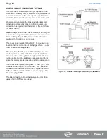
A bypass valve is mounted on the discharge of the foam pump. The bypass handle must be accessible by the pump oper-
ator during normal operations.
The bypass is a 3-way directional valve. Determine which port is the INJECT port and which port is the BYPASS (
Bypass hose connections are 1/2”. Hose fittings compatible with all foam concentrates must be provided. The hose from
the BYPASS port is plumbed to the atmosphere.
This hose is used for calibrating the foam pump, pumping the concentrate into a container to empty the foam tank or to
assist in priming of the foam pump. The hose from the BYPASS port must be long enough to reach a container outside
the truck.
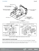
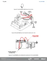
Models 3.3, 5.0, and 6.5
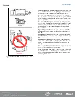
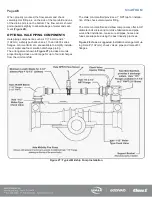
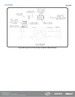
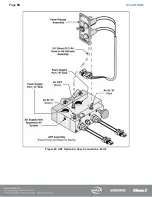
A bypass port is provided on the discharge side of the ADT, or a 1/4 turn bypass valve is mounted on the discharge of the
foam pump when the ADT option is not installed (
The bypass handle must be accessible by the pump operator during normal operations (
The bypass is a 3-way directional valve. Determine which port is the INJECT port and which port is the BYPASS (
). Bypass hose connections are 1/2-in (13 mm). Hose fittings compatible with all foam concentrates must be provided.
The hose from the BYPASS port is plumbed to the atmosphere and should not receive HIGH pressure.
This hose is used for calibrating the foam pump, pumping the
concentrate into a container to empty the foam tank or to assist in
priming of the foam pump. The hose from the BYPASS port must
be long enough to reach a container outside the truck.
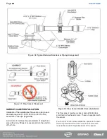
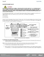
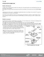
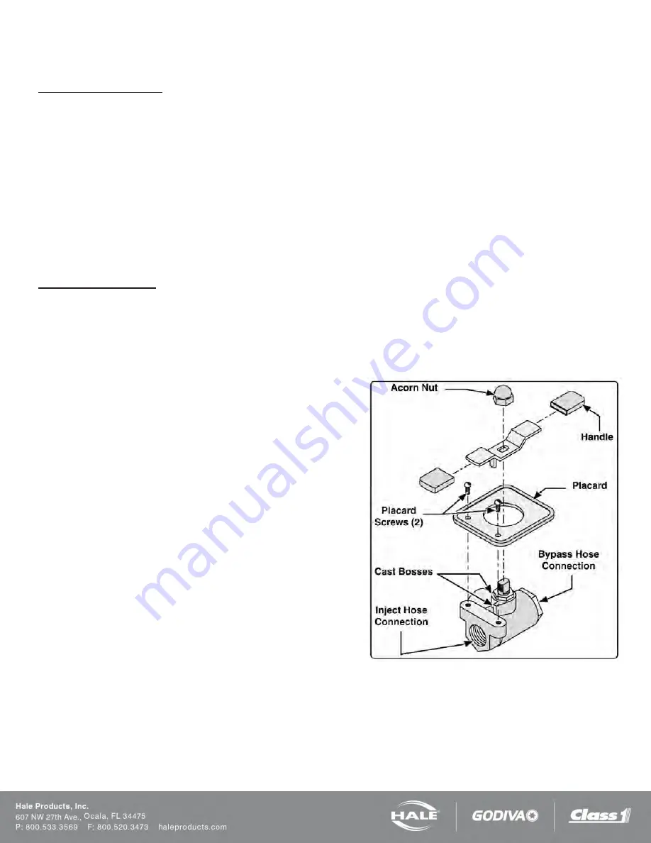
Note: If the handle or placard is removed from the bypass valve
for repairs or to facilitate remote mounting make sure they are in-
stalled on the valve correctly. Make sure the tang on the handle
engages the cast stops (Figure 40).
Figure 40: Bypass Valve Assembly
Содержание MiniCAFS 2.1A
Страница 3: ...Page 2 SmartFOAM NOTES...
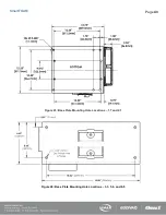
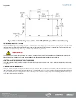
Страница 12: ...Page 11 SmartFOAM HALE FOAM PUMP DIMENSIONS Figure 1 1 7 and 2 1 Foam Pump Installation Envelope Dimensions...
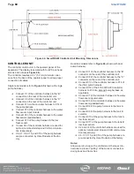
Страница 15: ...Page 14 SmartFOAM Figure 5 Converter Installation Envelope Dimensions Located Remote for 6 5 12VDC Systems...
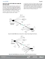
Страница 16: ...Page 15 SmartFOAM SYSTEM DIAGRAM Figure 6 Typical Hale SmartFOAM 2 1A and 1 7AHP System...
Страница 17: ...Page 16 SmartFOAM Figure 7 SmartFOAM 3 3 5 0 6 5 Single Tank System with In line Strainer...
Страница 18: ...Page 17 SmartFOAM Figure 8 SmartFOAM 3 3 5 0 6 5 Single Tank withMSTandIn lineStrainer...
Страница 19: ...Page 18 SmartFOAM Figure 9 SmartFOAM 3 3 5 0 6 5 Single Tank withMSTandFSSeriesStrainer...
Страница 20: ...Page 19 SmartFOAM Figure 10 SmartFOAM 3 3 5 0 6 5 Dual Tank withMDTIIandIn lineStrainers...
Страница 21: ...Page 20 SmartFOAM Figure 11 SmartFOAM 3 3 5 0 6 5 Dual Tank withMDTIIandFSSeriesStrainer...
Страница 22: ...Page 21 SmartFOAM Figure 12 SmartFOAM 3 3 5 0 6 5 Dual Tank withADTandIn lineStrainers...
Страница 23: ...Page 22 SmartFOAM Figure 13 SmartFOAM 3 3 5 0 6 5 Dual Tank withADTandFSSeries Strainers...
Страница 24: ...Page 23 SmartFOAM Figure 14 SmartFOAM Dual Pump 1 Single Tank with Valve Options and In Line Strainers...
Страница 25: ...Page 24 SmartFOAM Figure 15 SmartFOAM Dual Pump 1 Single Tank System with MST and FS Series Strainers...
Страница 26: ...Page 25 SmartFOAM Figure 16 SmartFOAM Dual Pump 1 Dual Tank System with MDT II and FS Series Strainers...
Страница 27: ...Page 26 SmartFOAM Figure 17 SmartFOAM Dual Pump 2 Single Tank System with valve options and In Line Strainers...
Страница 28: ...Page 27 SmartFOAM Figure 18 SmartFOAM Dual Pump 2 Single Tank System with MST and FS Series Strainers...
Страница 29: ...Page 28 SmartFOAM Figure 19 SmartFOAM Dual Pump 2 Dual Tank System with MDT II and FS Series Strainers...
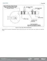
Страница 48: ...Page 47 SmartFOAM Figure 28 Typical 4 Inch Check Valve Installation Midship Pump...
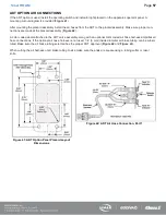
Страница 59: ...Page 58 SmartFOAM Figure 43 ADT Option Air Hose Connections Part 2...
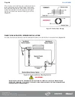
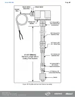
Страница 68: ...Page 67 SmartFOAM Figure 55 Top Mount Low Level Sensor Assembly...
Страница 77: ...Page 76 SmartFOAM NOTES...
Страница 90: ...89 Page 89 SmartFOAM NOTES...


