Page
92
SmartFOAM
TROUBLESHOOTING
USER DIAGNOSTICS
Diagnostic LED indicators are provided on the distribution
box and on the feedback sensor. The LED on the feedback
sensor flashes when the sensor is receiving pulses from the
flow sensor rotor targets. These LEDs help to ease tracing of
power supply faults and eliminates some of the guesswork
in troubleshooting. If the system malfunctions make sure the
following conditions are checked:
❑
All hose connections are correct and tight (Refer to
appropriate system plumbing diagram in the IN-
STALLATION section).
❑
All electrical connections are correct and tight (Refer
to appropriate system electrical diagram in the IN-
STALLATION section).
❑
Apparatus electrical system energized with power
supplied to pump panel and Hale SmartFOAM con-
troller.
Once the above conditions are met, proceed to the system
troubleshooting section to determine the cause of the mal-
function.
Hale SmartFOAM systems consist of individual subsystems
working together to provide finished foam solution at the
proper percentage. Also see the SYSTEM OVERVIEW sec-
tion.
The system is designed using modular components making
troubleshooting and repair easier. Each subsystem has its
own set of troubleshooting procedures. The procedures that
follow provide a logical flow path to isolate and correct a sys-
tem failure.
Note: Hale SmartFOAM system electronic components
have no user serviceable components inside and are re-
placed as a unit. Opening of Hale SmartFOAM electronic
components voids the manufacturer warranty.
System Overview
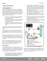
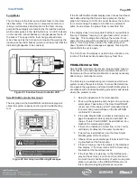
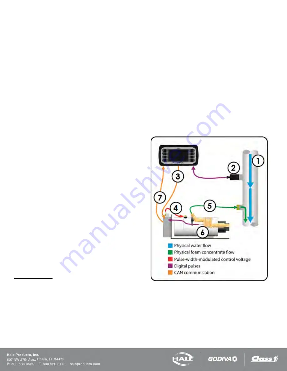
The SmartFOAM proportioner is a closed-loop system. The
“brain” behind the system is the computer-controlled Smart-
FOAM Controller Display. A basic understanding of how the
system functions makes troubleshooting easier (
while reading the following control steps).
1. Water flows through the discharge manifold and past
the water flow sensor spinning its paddlewheel.
2. The water flow sensor sends the raw digital pulses
to the SmartFOAM controller display.
3. The SmartFOAM controller display calculates the
desired foam flow rate based on the water flow rate
and the currently set foam concentrate percentage.
The SmartFOAM controller display transmits a re-
quested motor rate (0% to 100%) to the distribution
box via CAN communication.
4. The distribution box sends pulse-width-modulated
control voltage (0% to 100%) to the motor which
turns the pump at the desired speed.
5. The pump begins discharging foam concentrate into
the discharge manifold where it mixes with the wa-
ter.
6. The foam sensor detects the foam concentrate flow-
ing past the target rotors and sends the raw digital
pulses to the distribution box.
7. The distribution box sends the foam flow rate to the
SmartFOAM controller display where it is evaluated
and the process starts again at step 1.
Figure 80: Closed Loop Control Diagram
Note: The SmartFOAM system has a simulated flow func-
tion described in the SIMULATED FLOW OPERATION sec-
tion. This allows troubleshooting without flowing water yet
simulates an actual water flow.
Содержание MiniCAFS 2.1A
Страница 3: ...Page 2 SmartFOAM NOTES...
Страница 12: ...Page 11 SmartFOAM HALE FOAM PUMP DIMENSIONS Figure 1 1 7 and 2 1 Foam Pump Installation Envelope Dimensions...
Страница 15: ...Page 14 SmartFOAM Figure 5 Converter Installation Envelope Dimensions Located Remote for 6 5 12VDC Systems...
Страница 16: ...Page 15 SmartFOAM SYSTEM DIAGRAM Figure 6 Typical Hale SmartFOAM 2 1A and 1 7AHP System...
Страница 17: ...Page 16 SmartFOAM Figure 7 SmartFOAM 3 3 5 0 6 5 Single Tank System with In line Strainer...
Страница 18: ...Page 17 SmartFOAM Figure 8 SmartFOAM 3 3 5 0 6 5 Single Tank withMSTandIn lineStrainer...
Страница 19: ...Page 18 SmartFOAM Figure 9 SmartFOAM 3 3 5 0 6 5 Single Tank withMSTandFSSeriesStrainer...
Страница 20: ...Page 19 SmartFOAM Figure 10 SmartFOAM 3 3 5 0 6 5 Dual Tank withMDTIIandIn lineStrainers...
Страница 21: ...Page 20 SmartFOAM Figure 11 SmartFOAM 3 3 5 0 6 5 Dual Tank withMDTIIandFSSeriesStrainer...
Страница 22: ...Page 21 SmartFOAM Figure 12 SmartFOAM 3 3 5 0 6 5 Dual Tank withADTandIn lineStrainers...
Страница 23: ...Page 22 SmartFOAM Figure 13 SmartFOAM 3 3 5 0 6 5 Dual Tank withADTandFSSeries Strainers...
Страница 24: ...Page 23 SmartFOAM Figure 14 SmartFOAM Dual Pump 1 Single Tank with Valve Options and In Line Strainers...
Страница 25: ...Page 24 SmartFOAM Figure 15 SmartFOAM Dual Pump 1 Single Tank System with MST and FS Series Strainers...
Страница 26: ...Page 25 SmartFOAM Figure 16 SmartFOAM Dual Pump 1 Dual Tank System with MDT II and FS Series Strainers...
Страница 27: ...Page 26 SmartFOAM Figure 17 SmartFOAM Dual Pump 2 Single Tank System with valve options and In Line Strainers...
Страница 28: ...Page 27 SmartFOAM Figure 18 SmartFOAM Dual Pump 2 Single Tank System with MST and FS Series Strainers...
Страница 29: ...Page 28 SmartFOAM Figure 19 SmartFOAM Dual Pump 2 Dual Tank System with MDT II and FS Series Strainers...
Страница 48: ...Page 47 SmartFOAM Figure 28 Typical 4 Inch Check Valve Installation Midship Pump...
Страница 59: ...Page 58 SmartFOAM Figure 43 ADT Option Air Hose Connections Part 2...
Страница 68: ...Page 67 SmartFOAM Figure 55 Top Mount Low Level Sensor Assembly...
Страница 77: ...Page 76 SmartFOAM NOTES...
Страница 90: ...89 Page 89 SmartFOAM NOTES...

