
Page
33
SmartFOAM
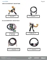
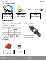
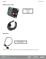
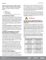
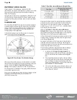
LOW TANK SENSOR OPTIONS
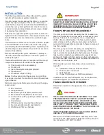
FLOW SENSOR OPTIONS
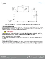
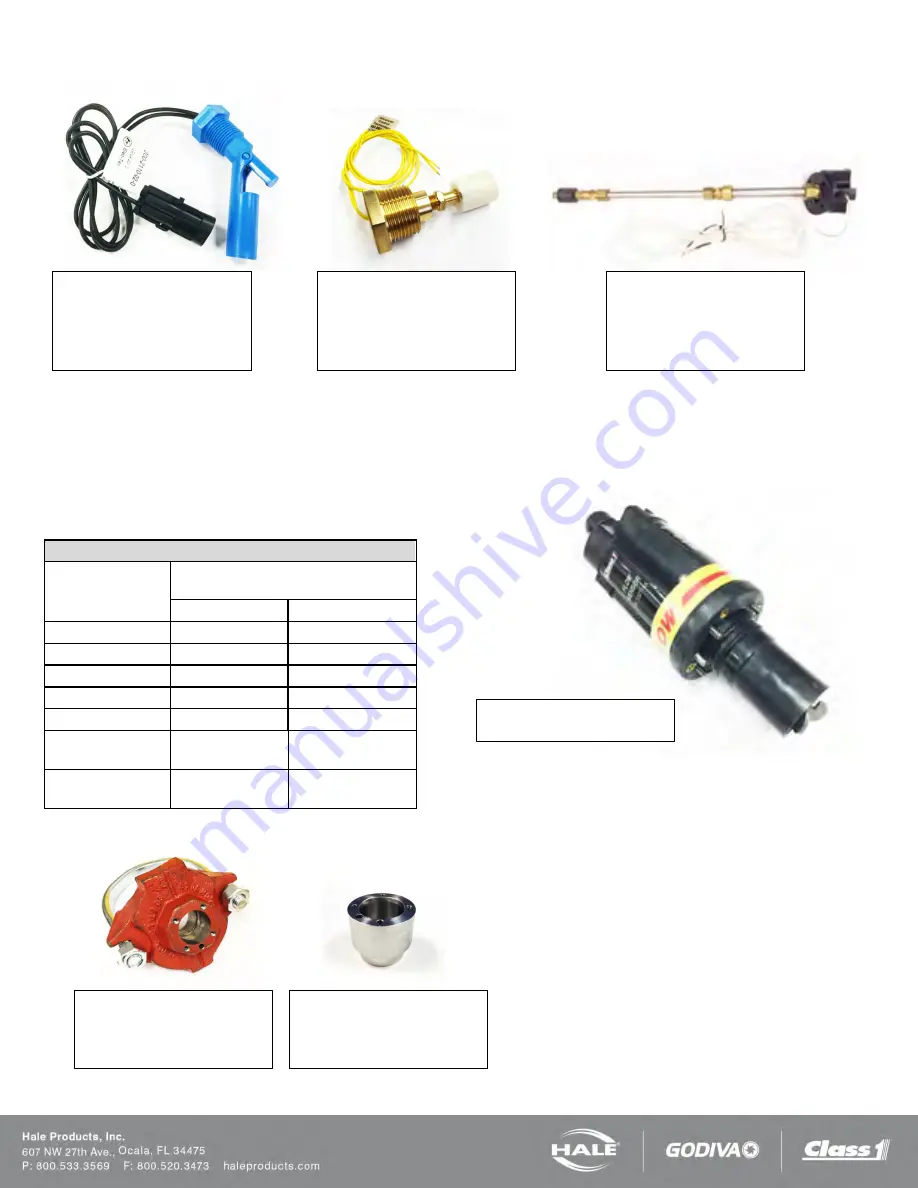
Each Hale foam system requires a flow sensor for operation. Pipe size must be selected based on the minimum and maxi-
mum water flow in the foam capable discharge. Following is a list of pipe size and rated flow ranges, along with flow sensor
saddle clamp part number. In all instances, a weld fitting may be substituted for the saddle clamp.
Table 5: Pipe Size Versus Flow Range
Pipe Size vs. Flow Range
Pipe size
Flow Range
GPM
LPM
1.5”
10 – 350
38 – 1,219
2.0”
20 – 550
76 – 2,082
2.5”
30 – 800
114 – 3,028
3.0”
50 – 1,250
189 – 4,731
4.0”
75 – 1,800
284 – 6,813
3” Single Check
Valve (SCV)
30 - 750
114 – 2,839
3” Dual Check Valve
(DCV)
30 - 750
114 – 2,839
Side mount (1/2 inch NPT)
200-2110-02-0
½ inch NPT threaded bushing to
mount from outside foam tank.
Bottom mount (1 inch NPT)
200-2100-04-0
1 inch NPT threaded bushing to
mount from outside foam tank
Top mount
200-2110-06-0
Extends from 2.5 feet to 5 feet –
may be cut shorter if required.
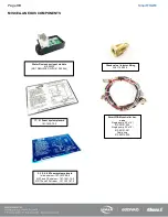
Flow sensor weld fitting
Stainless steel – 082-3060-00-0
Steel – 309020
Aluminum - 309010
Flow sensor saddle clamp
2.0 inch – 4842010
2.5 inch – 4843010
3.0 inch – 4844010
4.0 inch – 4846010
Flow sensor paddlewheel
102714
Содержание MiniCAFS 2.1A
Страница 3: ...Page 2 SmartFOAM NOTES...
Страница 12: ...Page 11 SmartFOAM HALE FOAM PUMP DIMENSIONS Figure 1 1 7 and 2 1 Foam Pump Installation Envelope Dimensions...
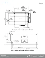
Страница 15: ...Page 14 SmartFOAM Figure 5 Converter Installation Envelope Dimensions Located Remote for 6 5 12VDC Systems...
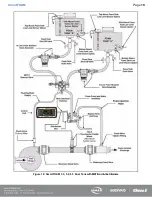
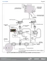
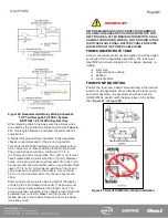
Страница 16: ...Page 15 SmartFOAM SYSTEM DIAGRAM Figure 6 Typical Hale SmartFOAM 2 1A and 1 7AHP System...
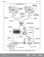
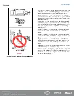
Страница 17: ...Page 16 SmartFOAM Figure 7 SmartFOAM 3 3 5 0 6 5 Single Tank System with In line Strainer...
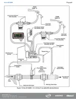
Страница 18: ...Page 17 SmartFOAM Figure 8 SmartFOAM 3 3 5 0 6 5 Single Tank withMSTandIn lineStrainer...
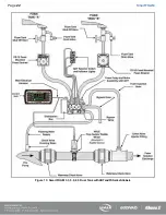
Страница 19: ...Page 18 SmartFOAM Figure 9 SmartFOAM 3 3 5 0 6 5 Single Tank withMSTandFSSeriesStrainer...
Страница 20: ...Page 19 SmartFOAM Figure 10 SmartFOAM 3 3 5 0 6 5 Dual Tank withMDTIIandIn lineStrainers...
Страница 21: ...Page 20 SmartFOAM Figure 11 SmartFOAM 3 3 5 0 6 5 Dual Tank withMDTIIandFSSeriesStrainer...
Страница 22: ...Page 21 SmartFOAM Figure 12 SmartFOAM 3 3 5 0 6 5 Dual Tank withADTandIn lineStrainers...
Страница 23: ...Page 22 SmartFOAM Figure 13 SmartFOAM 3 3 5 0 6 5 Dual Tank withADTandFSSeries Strainers...
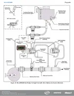
Страница 24: ...Page 23 SmartFOAM Figure 14 SmartFOAM Dual Pump 1 Single Tank with Valve Options and In Line Strainers...
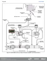
Страница 25: ...Page 24 SmartFOAM Figure 15 SmartFOAM Dual Pump 1 Single Tank System with MST and FS Series Strainers...
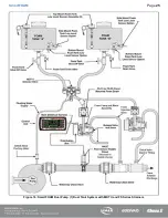
Страница 26: ...Page 25 SmartFOAM Figure 16 SmartFOAM Dual Pump 1 Dual Tank System with MDT II and FS Series Strainers...
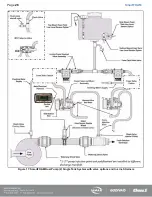
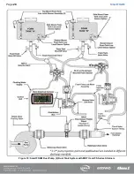
Страница 27: ...Page 26 SmartFOAM Figure 17 SmartFOAM Dual Pump 2 Single Tank System with valve options and In Line Strainers...
Страница 28: ...Page 27 SmartFOAM Figure 18 SmartFOAM Dual Pump 2 Single Tank System with MST and FS Series Strainers...
Страница 29: ...Page 28 SmartFOAM Figure 19 SmartFOAM Dual Pump 2 Dual Tank System with MDT II and FS Series Strainers...
Страница 48: ...Page 47 SmartFOAM Figure 28 Typical 4 Inch Check Valve Installation Midship Pump...
Страница 59: ...Page 58 SmartFOAM Figure 43 ADT Option Air Hose Connections Part 2...
Страница 68: ...Page 67 SmartFOAM Figure 55 Top Mount Low Level Sensor Assembly...
Страница 77: ...Page 76 SmartFOAM NOTES...
Страница 90: ...89 Page 89 SmartFOAM NOTES...


