


Page
6
SmartFOAM
SAFETY
IMPORTANT!
ALL HALE SMARTFOAM MODELS ELECTRONIC
FOAM PROPORTIONING SYSTEMS ARE DE-
SIGNED FOR OPTIMUM SAFETY OF ITS OPERA-
TORS AND TO PROVIDE RELIABLE AND SAFE
FOAM CONCENTRATE INJECTION. FOR ADDED
PROTECTION AND BEFORE ATTEMPTING INSTAL-
LATION OR OPERATION PLEASE FOLLOW THE
SAFETY GUIDELINES LISTED IN THIS SECTION
AND ADHERE TO ALL WARNING, DANGER, CAU-
TION AND IMPORTANT NOTES FOUND WITHIN
THIS GUIDE.
THIS SECTION ON SAFETY MUST BE CAREFULLY
READ, UNDERSTOOD AND ADHERED TO
STRICTLY BY ALL INSTALLERS AND OPERATORS
BEFORE ATTEMPTING TO INSTALL OR OPERATE
THE SMARTFOAM PROPORTIONING SYSTEM.
INCORPORATE THE WARNINGS AND CAUTIONS
AS WRITTEN WHEN DEVELOPING DEPART-
MENTAL APPARATUS OPERATING PROCEDURES.
SmartFOAM is a trademark of Hale Products, In-
corporated. All other brand and product names are
the trademarks of their respective
holders.
GUIDELINES
READ ALL INSTRUCTIONS THOROUGHLY BEFORE
BEGINNING ANY INSTALLATION OR OPERATION
PROCESS.
❑
Installation should be performed by a trained and
qualified installer, or your authorized Hale Prod-
ucts service representative.
❑
Be sure the installer has sufficient knowledge, ex-
perience and the proper tools before attempting
any installation.
❑
Make sure proper personal protective equipment is
used when operating or servicing apparatus.
❑
A foam tank low level sensor must be utilized to
protect the Hale Foam proportioner from dry run-
ning.
Failure to use a low level sensor with the
Hale Foam system voids warranty.
❑
DO NOT permanently remove or alter any
guard or insulating devices, or attempt to op-
erate the system when these guards are re-
moved.
❑
Make sure all access/service panels and covers
are installed, closed and latched tight, where ap-
plicable.
❑
DO NOT remove or alter any hydraulic or pneu-
matic connections, electrical devices, etc. DO
NOT tamper with or disconnect safety features or
modify protective guards (such as covers or
doors). DO NOT add or remove structural parts.
Doing so voids the warranty.
Any of the above could affect system capacity and/or
safe operation of the system and is a serious safety
violation which could cause personal injury, could
weaken the construction of the system or could affect
safe operation of the SmartFOAM Proportioning Sys-
tem.
WARNING!
NO MODIFICATIONS OR ADDITIONS MAY BE
MADE TO THE SMARTFOAM PORPORTIONING
SYSTEM WITHOUT PRIOR WRITTEN PERMISSION
FROM:
HALE PRODUCTS, INC
607 NW 27
th
Avenue
Ocala, Florida 34475 USA
Telephone: 352-629-5020
FAX: 800-533-3569
❑
All electrical systems have the potential to
cause sparks during service. Take care to elimi-
nate explosive or hazardous environments dur-
ing service and/or repair.
❑
To prevent electrical shock always disconnect the
primary power source before attempting to service
any part of the Hale Foam system.
❑
To prevent system damage or electrical shock
the main power supply wire is the last connec-
tion made to the Hale Foam motor controller.
❑
Release all pressure then drain all concentrate and
water from the system before servicing any of its
component parts.
Содержание MiniCAFS 2.1A
Страница 3: ...Page 2 SmartFOAM NOTES...
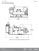
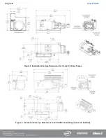
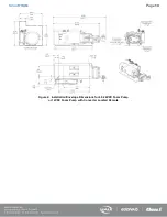
Страница 12: ...Page 11 SmartFOAM HALE FOAM PUMP DIMENSIONS Figure 1 1 7 and 2 1 Foam Pump Installation Envelope Dimensions...
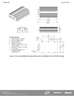
Страница 15: ...Page 14 SmartFOAM Figure 5 Converter Installation Envelope Dimensions Located Remote for 6 5 12VDC Systems...
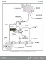
Страница 16: ...Page 15 SmartFOAM SYSTEM DIAGRAM Figure 6 Typical Hale SmartFOAM 2 1A and 1 7AHP System...
Страница 17: ...Page 16 SmartFOAM Figure 7 SmartFOAM 3 3 5 0 6 5 Single Tank System with In line Strainer...
Страница 18: ...Page 17 SmartFOAM Figure 8 SmartFOAM 3 3 5 0 6 5 Single Tank withMSTandIn lineStrainer...
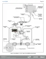
Страница 19: ...Page 18 SmartFOAM Figure 9 SmartFOAM 3 3 5 0 6 5 Single Tank withMSTandFSSeriesStrainer...
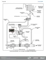
Страница 20: ...Page 19 SmartFOAM Figure 10 SmartFOAM 3 3 5 0 6 5 Dual Tank withMDTIIandIn lineStrainers...
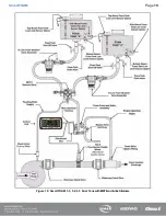
Страница 21: ...Page 20 SmartFOAM Figure 11 SmartFOAM 3 3 5 0 6 5 Dual Tank withMDTIIandFSSeriesStrainer...
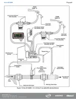
Страница 22: ...Page 21 SmartFOAM Figure 12 SmartFOAM 3 3 5 0 6 5 Dual Tank withADTandIn lineStrainers...
Страница 23: ...Page 22 SmartFOAM Figure 13 SmartFOAM 3 3 5 0 6 5 Dual Tank withADTandFSSeries Strainers...
Страница 24: ...Page 23 SmartFOAM Figure 14 SmartFOAM Dual Pump 1 Single Tank with Valve Options and In Line Strainers...
Страница 25: ...Page 24 SmartFOAM Figure 15 SmartFOAM Dual Pump 1 Single Tank System with MST and FS Series Strainers...
Страница 26: ...Page 25 SmartFOAM Figure 16 SmartFOAM Dual Pump 1 Dual Tank System with MDT II and FS Series Strainers...
Страница 27: ...Page 26 SmartFOAM Figure 17 SmartFOAM Dual Pump 2 Single Tank System with valve options and In Line Strainers...
Страница 28: ...Page 27 SmartFOAM Figure 18 SmartFOAM Dual Pump 2 Single Tank System with MST and FS Series Strainers...
Страница 29: ...Page 28 SmartFOAM Figure 19 SmartFOAM Dual Pump 2 Dual Tank System with MDT II and FS Series Strainers...
Страница 48: ...Page 47 SmartFOAM Figure 28 Typical 4 Inch Check Valve Installation Midship Pump...
Страница 59: ...Page 58 SmartFOAM Figure 43 ADT Option Air Hose Connections Part 2...
Страница 68: ...Page 67 SmartFOAM Figure 55 Top Mount Low Level Sensor Assembly...
Страница 77: ...Page 76 SmartFOAM NOTES...
Страница 90: ...89 Page 89 SmartFOAM NOTES...


