95
Page
95
SmartFOAM
Pump/Motor
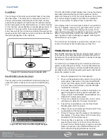
The discharge of the foam pump directs foam to the rotary
lobe flow meter. The rotors are a composite material con-
taining small stainless steel targets. As the foam is being
pumped these targets are detected by the inductive sensor
which sends pulses to the distribution box. An LED indicator
on the inductive sensor flashes as a target passes the tip of
the sensor. The speed of the foam being pumped deter-
mines how quickly the rotors are turning and how quickly the
inductive sensor LED flashes (which could be so fast that the
indicator light appears to be constant).
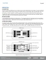
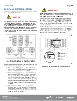
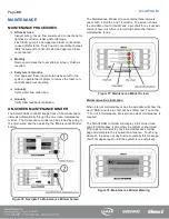
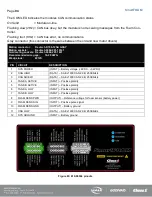
Figure 84: Inductive Sensor Indicator LED
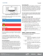
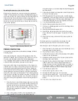
SmartFOAM Controller Bar Graph
The bar graph on the SmartFOAM controller display indi-
cates the system capacity and is a good troubleshooting
tool.
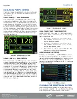
Figure 85: Bar Graph and Warning Messages
If the SmartFOAM controller display does not see foam feed-
back data indicating that foam is being pumped, the bar
graph will increase to 100% (full scale) because the control-
ler is commanding the pump to turn fast in an attempt to
prime it and achieve the proper foam concentrate flow.
If the display does not receive data that foam concentrate is
flowing, it displays “ramping to re-gain foam prime” caution
message. This message also displays the number of sec-
onds until the pump will be turned OFF if prime is not estab-
lished. If the timer times out then the “foam pump shut
down” operation halted message will appear. Pressing ON
button starts the cycle again.
The Total Foam flow display is useful in this scenario to de-
termine if the foam sensor is detecting any foam flow.
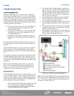
PROBLEM ISOLATION
SmartFOAM replacement parts are “plug and play” type de-
vices that do not require specialized equipment to service.
Normal water flow and foam calibration is usually necessary
after a major component service.
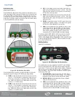
The first step in troubleshooting is to determine which sub-
system caused the system failure. To make this determina-
tion operate the apparatus and Hale SmartFOAM system in
accordance with standard operating procedures and isolate
where the problem occurs.
1. Setup the apparatus for normal operation.
2. Power-up the apparatus and energize the pump op-
erator panel. Take notice of the Hale SmartFOAM
control unit. If the display is NOT illuminated check
for power and ground voltage on the SmartFOAM
controller “B” connector.
3. If the Hale SmartFOAM controller is illuminated, en-
gage the apparatus water pump and establish dis-
charge. If water flow CANNOT be established, trou-
bleshoot the water pump system.
4. If there is no indication of water flow on the control
unit display troubleshoot the water flow sensor.
5. If water flow is established, turn the Hale Smart-
FOAM system ON to flow foam.
6. Observe foam pump discharge. If foam is NOT flow-
ing troubleshoot the foam pump.
7. If foam is flowing, check the status of the total foam
flow display. If the foam total is NOT incrementing
troubleshoot the foam flow sensor.
8. If the foam flow is registering on the total foam dis-
play but the accuracy is not correct (too little foam /
too much foam) check accuracy of system using cali-
bration procedures in the OPERATION section of
this manual making adjustments as required.
Содержание MiniCAFS 2.1A
Страница 3: ...Page 2 SmartFOAM NOTES...
Страница 12: ...Page 11 SmartFOAM HALE FOAM PUMP DIMENSIONS Figure 1 1 7 and 2 1 Foam Pump Installation Envelope Dimensions...
Страница 15: ...Page 14 SmartFOAM Figure 5 Converter Installation Envelope Dimensions Located Remote for 6 5 12VDC Systems...
Страница 16: ...Page 15 SmartFOAM SYSTEM DIAGRAM Figure 6 Typical Hale SmartFOAM 2 1A and 1 7AHP System...
Страница 17: ...Page 16 SmartFOAM Figure 7 SmartFOAM 3 3 5 0 6 5 Single Tank System with In line Strainer...
Страница 18: ...Page 17 SmartFOAM Figure 8 SmartFOAM 3 3 5 0 6 5 Single Tank withMSTandIn lineStrainer...
Страница 19: ...Page 18 SmartFOAM Figure 9 SmartFOAM 3 3 5 0 6 5 Single Tank withMSTandFSSeriesStrainer...
Страница 20: ...Page 19 SmartFOAM Figure 10 SmartFOAM 3 3 5 0 6 5 Dual Tank withMDTIIandIn lineStrainers...
Страница 21: ...Page 20 SmartFOAM Figure 11 SmartFOAM 3 3 5 0 6 5 Dual Tank withMDTIIandFSSeriesStrainer...
Страница 22: ...Page 21 SmartFOAM Figure 12 SmartFOAM 3 3 5 0 6 5 Dual Tank withADTandIn lineStrainers...
Страница 23: ...Page 22 SmartFOAM Figure 13 SmartFOAM 3 3 5 0 6 5 Dual Tank withADTandFSSeries Strainers...
Страница 24: ...Page 23 SmartFOAM Figure 14 SmartFOAM Dual Pump 1 Single Tank with Valve Options and In Line Strainers...
Страница 25: ...Page 24 SmartFOAM Figure 15 SmartFOAM Dual Pump 1 Single Tank System with MST and FS Series Strainers...
Страница 26: ...Page 25 SmartFOAM Figure 16 SmartFOAM Dual Pump 1 Dual Tank System with MDT II and FS Series Strainers...
Страница 27: ...Page 26 SmartFOAM Figure 17 SmartFOAM Dual Pump 2 Single Tank System with valve options and In Line Strainers...
Страница 28: ...Page 27 SmartFOAM Figure 18 SmartFOAM Dual Pump 2 Single Tank System with MST and FS Series Strainers...
Страница 29: ...Page 28 SmartFOAM Figure 19 SmartFOAM Dual Pump 2 Dual Tank System with MDT II and FS Series Strainers...
Страница 48: ...Page 47 SmartFOAM Figure 28 Typical 4 Inch Check Valve Installation Midship Pump...
Страница 59: ...Page 58 SmartFOAM Figure 43 ADT Option Air Hose Connections Part 2...
Страница 68: ...Page 67 SmartFOAM Figure 55 Top Mount Low Level Sensor Assembly...
Страница 77: ...Page 76 SmartFOAM NOTES...
Страница 90: ...89 Page 89 SmartFOAM NOTES...

