Page
78
SmartFOAM
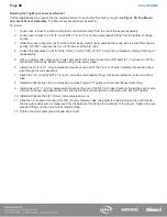
These flow points are arbitrary and can be selected at
any two points within the operation range of the dis-
charge.
1. Determine the desired high rate water flow nor-
mally expected from the discharge outlet and es-
tablish flow.
a. Make sure the water flow established is
within the range of the flow sensor moni-
toring the discharge.
For example, establish a flow rate of 150
GPM (568 LPM) of water through a noz-
zle and Pitot system. Compare the cal-
culated flow value to the value shown on
the control unit display.
2. Press the INCR/DECR buttons to set the dis-
played high flow value to match the actual flow
through the discharge.
3. Press the SET button to associate the water flow
sensors (paddlewheel) pulse rate with the high
flow value.
4. Determine the desired low rate water flow nor-
mally expected from the discharge outlet and es-
tablish flow.
5. Press the INCR/DECR buttons to set the dis-
played low flow value to match the actual flow
through the discharge.
6. Press the SET button to associate the water flow
sensors (paddlewheel) pulse rate with the low
flow value.
7. Press the SAVE button to save the flow values
into non-volatile memory.
Record the calibrated values in the section below.
These values can be entered manually if the controller
unit ever needs to be replaced.
Flow Rate
Flow Pulses
High rate cal.
Low rate cal.
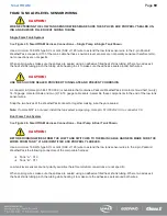
FOAM FLOW CALIBRATION
IMPORTANT!
FOAM PUMP FEEDBACK IS CALIBRATED AFTER INSTAL-
LATION TO VERIFY VALUES WITH THE ACTUAL FOAM
CONCENTRATE BEING USED. ONLY CALIBRATE USING
ACTUAL FOAM CONCENTRATES.
DO NOT USE WATER, TRAINING OR TEST FOAMS FOR
FEEDBACK CALIBRATION VERIFICATION.
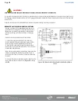
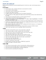
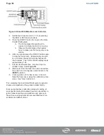
Enter the password “1560”. The controller will show the foam
flow calibration screen.
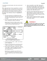
1. Set the bypass valves handle to
BYPASS
.
2. Place a graduated measure container at the outlet of the
bypass hose capable of containing the expected volume
of foam concentrate: 5 gallons (19 liters) minimum.
3. Start the Hale SmartFOAM foam pump by pressing the
ON/OFF button.
4. Watch the level of foam in the graduated measure con-
tainer and stop the foam pump when at the desired level
by pressing the ON/OFF button again.
5. Adjust the reading on the display to match the actual
volume by using the INCR and DECR arrow buttons.
6. Press the SAVE button.
7. Repeat the procedure to verify that the setting is correct.
a. Press the SAVE button again if the value was
modified.
8. Set the bypass valves handle back to
INJECT
.
Record the calibrated values in the section below.
Foam factor
Содержание MiniCAFS 2.1A
Страница 3: ...Page 2 SmartFOAM NOTES...
Страница 12: ...Page 11 SmartFOAM HALE FOAM PUMP DIMENSIONS Figure 1 1 7 and 2 1 Foam Pump Installation Envelope Dimensions...
Страница 15: ...Page 14 SmartFOAM Figure 5 Converter Installation Envelope Dimensions Located Remote for 6 5 12VDC Systems...
Страница 16: ...Page 15 SmartFOAM SYSTEM DIAGRAM Figure 6 Typical Hale SmartFOAM 2 1A and 1 7AHP System...
Страница 17: ...Page 16 SmartFOAM Figure 7 SmartFOAM 3 3 5 0 6 5 Single Tank System with In line Strainer...
Страница 18: ...Page 17 SmartFOAM Figure 8 SmartFOAM 3 3 5 0 6 5 Single Tank withMSTandIn lineStrainer...
Страница 19: ...Page 18 SmartFOAM Figure 9 SmartFOAM 3 3 5 0 6 5 Single Tank withMSTandFSSeriesStrainer...
Страница 20: ...Page 19 SmartFOAM Figure 10 SmartFOAM 3 3 5 0 6 5 Dual Tank withMDTIIandIn lineStrainers...
Страница 21: ...Page 20 SmartFOAM Figure 11 SmartFOAM 3 3 5 0 6 5 Dual Tank withMDTIIandFSSeriesStrainer...
Страница 22: ...Page 21 SmartFOAM Figure 12 SmartFOAM 3 3 5 0 6 5 Dual Tank withADTandIn lineStrainers...
Страница 23: ...Page 22 SmartFOAM Figure 13 SmartFOAM 3 3 5 0 6 5 Dual Tank withADTandFSSeries Strainers...
Страница 24: ...Page 23 SmartFOAM Figure 14 SmartFOAM Dual Pump 1 Single Tank with Valve Options and In Line Strainers...
Страница 25: ...Page 24 SmartFOAM Figure 15 SmartFOAM Dual Pump 1 Single Tank System with MST and FS Series Strainers...
Страница 26: ...Page 25 SmartFOAM Figure 16 SmartFOAM Dual Pump 1 Dual Tank System with MDT II and FS Series Strainers...
Страница 27: ...Page 26 SmartFOAM Figure 17 SmartFOAM Dual Pump 2 Single Tank System with valve options and In Line Strainers...
Страница 28: ...Page 27 SmartFOAM Figure 18 SmartFOAM Dual Pump 2 Single Tank System with MST and FS Series Strainers...
Страница 29: ...Page 28 SmartFOAM Figure 19 SmartFOAM Dual Pump 2 Dual Tank System with MDT II and FS Series Strainers...
Страница 48: ...Page 47 SmartFOAM Figure 28 Typical 4 Inch Check Valve Installation Midship Pump...
Страница 59: ...Page 58 SmartFOAM Figure 43 ADT Option Air Hose Connections Part 2...
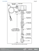
Страница 68: ...Page 67 SmartFOAM Figure 55 Top Mount Low Level Sensor Assembly...
Страница 77: ...Page 76 SmartFOAM NOTES...
Страница 90: ...89 Page 89 SmartFOAM NOTES...

