CS610-UM-251-9370
8-17
8. DISASSEMBLING AND ADJUSTING THE MECHANICAL PARTS
8.13 CIS (Charge Coupled Device Imaging Sensor) Assembly
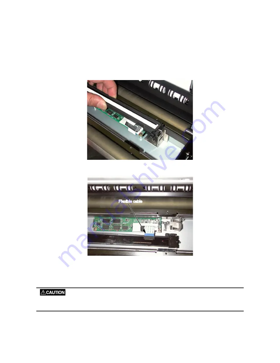
Detaching the CIS assembly
(1) Detach the contact glass assembly (see Section 8.12).
(2) Slide each CIS assembly to the left side, lift it up from the right side, and then detach each CIS
assembly.
(3) Disconnect the flexible cable from each CIS assembly and then detach each CIS assembly.
Flexible cable
Flexible cable
Reattaching the CIS assembly
(1) Reattach each CIS assembly in the reverse order in which it was detached.
(2) Perform the software adjustment.
When replacing the CIS assembly, be sure to clean the interior of the image sensor unit and the inside of the
contact glass assembly. A soiled or dusty unit can affect scanning performance.
Содержание CS610-11eN
Страница 1: ...COLORIMAGESCANNER SERVICE MANUAL CS610 SERIES CS610 UM251 02 9370...
Страница 2: ......
Страница 42: ......
Страница 44: ......
Страница 118: ......
Страница 120: ......
Страница 123: ...CS610 UM 251 9370 13 3 13 PARTS LIST Main Frame 1 7 6 4 Ethernet board Enhanced I F board 8 9 3 5 2...
Страница 128: ...13 PARTS LIST CS610 UM 251 9370 13 8 CIS Unit 6 4 2 11 9 10 12 8 1 3 5 7...
Страница 130: ...13 PARTS LIST CS610 UM 251 9370 13 10 Top Cover 3 5 2 9 6 10 7 4 8 8 10 11 12 12 12 13 14 15 16 1...


