CS610-UM-251-9370
10-15
10. ADJUSTMENTS USING THE SOFTWARE
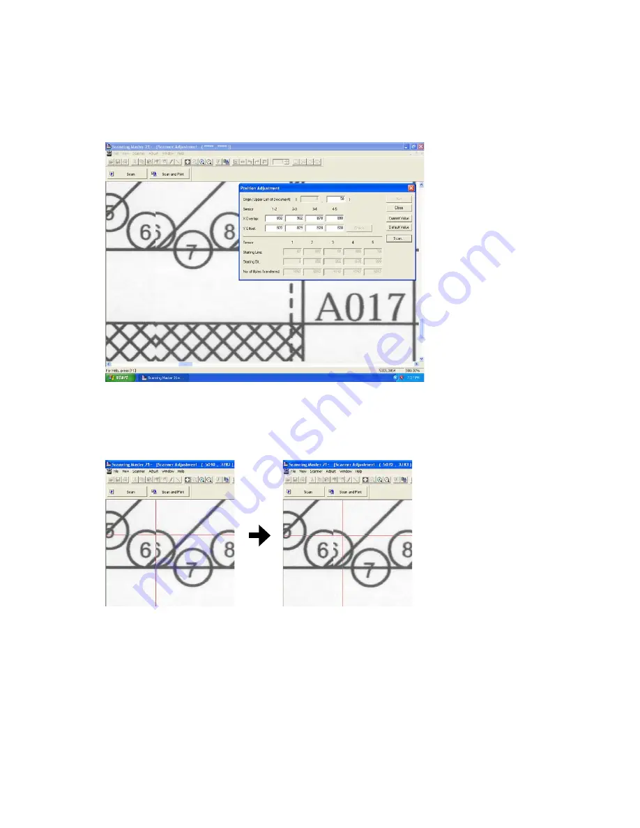
(7) The image appears as shown below.
Then confirm the jointing area of sensors from the A area to E area.
At this time, confirm around 017 lines, because the top part of target is not stable to contact the CIS
sensors.
(8) The image appears as shown above with the left-hand portion of the image misaligned with the right-
hand portion.
Click anywhere in the X Overlap box under "1-2" (A area).
(9) The crosshairs cursor will appear. First click a position on the left-hand portion, then click the position of
the right-hand portion that corresponds to the position you selected first.
(10) Click the "Check" button first, then click the "Set" button. Follow the on-screen instruction to place the
adjustment chart on the scanner again.
(11) Repeat these steps until the left-hand portion is properly aligned with the right-hand portion.
In this task, you need to adjust the X overlap and Y offset at the same time.
See "Tips for Making Fine Adjustments" on the next page if you encounter difficulties making fine
adjustments.
(12) Similarly, make adjustments for 2-3 (B area), 3-4 (D area), and 4-5 (E area) in this order if there is
misaligned.
After finishing, close all the adjustment menu windows. Use the CS600/500/IS200 Test Chart to perform
a normal scan, and confirm that the image appears properly.
Содержание CS610-11eN
Страница 1: ...COLORIMAGESCANNER SERVICE MANUAL CS610 SERIES CS610 UM251 02 9370...
Страница 2: ......
Страница 42: ......
Страница 44: ......
Страница 118: ......
Страница 120: ......
Страница 123: ...CS610 UM 251 9370 13 3 13 PARTS LIST Main Frame 1 7 6 4 Ethernet board Enhanced I F board 8 9 3 5 2...
Страница 128: ...13 PARTS LIST CS610 UM 251 9370 13 8 CIS Unit 6 4 2 11 9 10 12 8 1 3 5 7...
Страница 130: ...13 PARTS LIST CS610 UM 251 9370 13 10 Top Cover 3 5 2 9 6 10 7 4 8 8 10 11 12 12 12 13 14 15 16 1...


