


Brivo OEC 715/785/865 Mobile C-Arm X-Ray Product
Page 3-9
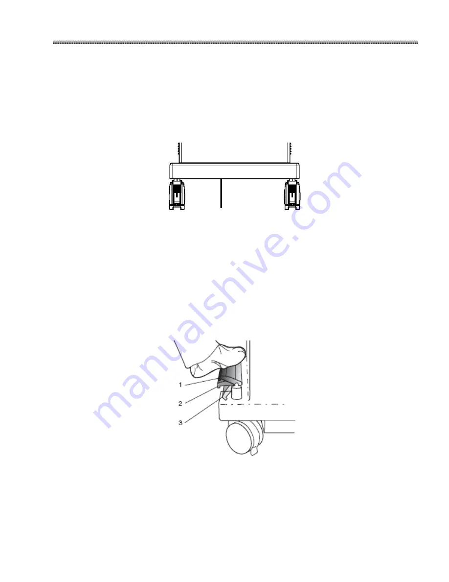
3.2.9.
Workstation Brakes
Brivo OEC 715/785 Workstation provides wheel brakes. Pressing the wheel brakes allows you to lock the
brakes and prevent the Workstation from moving.
Unlock the brakes by pressing down the wheel brakes again.
Brivo OEC 865 Workstation provides brake pedal located on the left side of the Workstation. It has three
positions that control wheel movement. The pedal positions are:
1.
The wheels close to the pedal roll in a straight line, and the wheels opposite pivot freely. Place the brake
pedal this position to move the Workstation long distances.
2.
Allows all the wheels to pivot freely. Place the brake pedal in this position to easily maneuver the
Workstation during final positioning.
3.
Prevents Workstation from moving.
Содержание Brivo OEC 715
Страница 9: ...Chapter1 Introduction and Safety...
Страница 34: ...Chapter2 System Overview...
Страница 36: ...Brivo OEC 715 785 865 Mobile C Arm X Ray Product Page 2 3 2 2 C Arm Components...
Страница 38: ...Brivo OEC 715 785 865 Mobile C Arm X Ray Product Page 2 5 2 3 Workstation Components...
Страница 40: ...Chapter3 Mechanical Positioning...
Страница 52: ...Chapter4 Start Up and Operating Control...
Страница 77: ...Chapter5 Usual Operations...
Страница 108: ...Chapter6 SpecialApplications...
Страница 139: ...Chapter7 Radiographic Film...
Страница 142: ...Chapter8 System Setup...
Страница 149: ...System Setup Page 8 8 Click any mouse button to return to normal screen...
Страница 150: ...Chapter9 Maintenance...
Страница 160: ...Chapter10 Display Messages...
Страница 162: ...Chapter11 Labels and Symbols...
Страница 167: ...Labels and Symbols Page 11 6 18 1 System rating plate indicates manufacture information and input power requirements...
Страница 168: ...Brivo OEC 715 785 865 Mobile C Arm X Ray Product Page 11 7 19 1 X ray Generator rating plate Total Filtration label...
Страница 177: ...Labels and Symbols Page 11 16 42 12 15 29 40 15 13 10 18 39 31 27 24 23 37 38...
Страница 179: ...Chapter12 Technical Reference...
Страница 183: ...Brivo OEC 715 785 865 Mobile C Arm X Ray Product Page 12 5 Workstation Weight 170 10kg...
Страница 194: ...Technical Reference Page 12 16 Lateral configuration 1 5m LOHMANN Lateral configuration 1m LOHMANN...
Страница 206: ...Technical Reference Page 12 28 12 11 System Block...
Страница 209: ......
Страница 210: ...www gehealthcare com Imagination at work...


