


13-9-666 Page 55
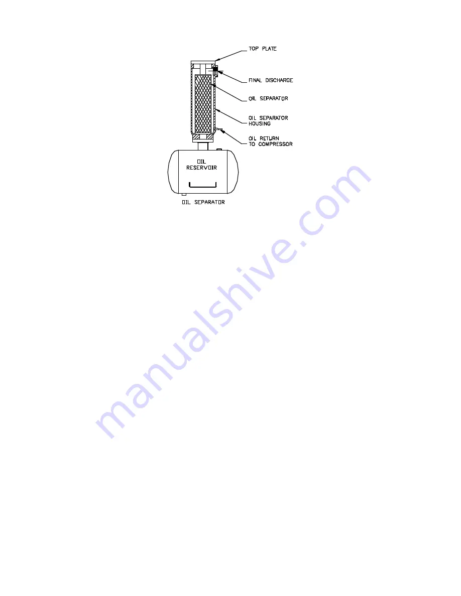
Figure 5-11 – OIL SEPARATOR
COMPRESSOR (GD ELIMINATOR) OIL SEPARATOR
located in a separate housing, consists of a
renewable cartridge-type separator element and provides the final removal of oil from the air stream
(Figure 5-11).
Oil impinging on the inside of the separator element drains directly back into the oil reservoir by gravity.
Oil collected outside the element is returned through tubing to the compressor cylinder.
Oil carryover
through the service lines may be caused by a faulty oil separator, faulty minimum pressure
valve, over-filling of the oil reservoir, oil that foams, oil return line malfunction or water condensate in the
oil. If oil carryover occurs, inspect the separator only after it is determined that the oil level is not too high,
the oil is not foaming excessively, the oil return line from the separator housing to the compressor cylinder
is not clogged or pinched off, the check valve in the oil return line is functioning properly, and there is not
water or an oil/water emulsion in the oil.
Oil carryover malfunctions of the oil separator are usually due to using elements too long, heavy dirt or
varnish deposits caused by inadequate air filter service, use of improper oil or using oil too long for
existing conditions. A ruptured or collapsed separator element is usually due to heavy dirt or varnish
buildup in the filtering material. Excessive tilt angle of the unit will also hamper separation and cause oil
carryover.
Oil separator element life cannot be predicted; it will vary greatly depending on the conditions of
operation, the quality of the oil used and the maintenance of the oil and air filters. The condition of the
separator can be determined by pressure differential gauging or by inspection.
Pressure Differential Gauging
- The “CHANGE SEPARATOR” advisory will flash when the pressure
differential across the oil separator reaches approximately 8 psid (.55 bar). Replace the oil separator
element at this time. If ignored, the unit will shut down and the advisory will illuminate steadily when the
pressure differential reaches 15 psid (1 bar).
Содержание ELECTRA-SAVER EAQ99Q
Страница 10: ...13 9 666 Page 3 Figure 1 4 COMPRESSOR MOTOR SIDE Figure 1 5 COOLER RESERVOIR SIDE 200EDM797 A Ref Drawing...
Страница 11: ...13 9 666 Page 4 Figure 1 6 AIR OIL FLOW DIAGRAM 202EDM797 Ref Drawing...
Страница 13: ...13 9 666 Page 6 DECALS 206EAQ077 212EAQ077 218EAQ077 211EAQ077 207EAQ077...
Страница 14: ...13 9 666 Page 7 DECALS 216EAQ077 217EAQ077 222EAQ077 221EAQ077 208EAQ077...
Страница 43: ...13 9 666 Page 36 Figure 4 13 WIRING DIAGRAM WYE DELTA EBQ EBU UNITS 300EDM546 A Ref Drawing...
Страница 44: ...13 9 666 Page 37 Figure 4 14 WIRING DIAGRAM FULL VOLTAGE EBQ EBU UNITS...
Страница 45: ...13 9 666 Page 38 Figure 4 15 WIRING DIAGRAM WYE DELTA EAQ EAU UNITS ONLY 301EAQ546 B Ref Drawing...
Страница 46: ...13 9 666 Page 39 Figure 4 16 WIRING DIAGRAM FULL VOLTAGE EAQ EAU UNITS ONLY 303EAQ546 Ref Drawing...
Страница 50: ...13 9 666 Page 43 Figure 5 3 FLOW DIAGRAM AIR OIL SYSTEM 203EDM797 A Ref Drawing...