background image

CX400 M4

Upgrade and Maintenance Manual

29

Important information

Batteries must be disposed of in accordance with local regulations 
concerning special waste.

Make sure that you insert the battery the right way round.

The battery used in this server enclosure may present a fire or chemical burn 
hazard if mistreated. Do not disassemble, heat about 100 °C (212F), or 
incinerate the battery.

Replace the lithium battery on the system board in accordance with the 
instructions in the corresponding Upgrade and Maintenance Manual, 
chapter "System board and components" > "CMOS battery". 

All batteries containing pollutants are marked with a symbol (a crossed-out 
garbage can). In addition, the marking is provided with the chemical symbol 
of the heavy metal decisive for the classification as a pollutant:

Cd Cadmium 
Hg Mercury 
Pb Lead

Working with optical disk drives and media

When working with optical disk drives, these instructions must be followed.

V

CAUTION!

Only use CDs/DVDs/BDs that are in perfect condition, in order to 
prevent data loss, equipment damage and injury.

Check each CD/DVD/BD for damage, cracks, breakages etc. before 
inserting it in the drive.

Note that any additional labels applied may change the mechanical 
properties of a CD/DVD/BD and cause imbalance and vibrations.

Damaged and imbalanced CDs/DVDs/BDs can break at high drive 
speeds (data loss).

Under certain circumstances, sharp CD/DVD/BD fragments can 
pierce the cover of the optical disk drive (equipment damage) and can 
fly out of the drive (danger of injury, particularly to uncovered body 
parts such as the face or neck).

High humidity and airborne dust levels are to be avoided. Electric 
shocks and/or server enclosure failures may be caused by liquids 
such as water, or metallic items, such as paper clips, entering a drive.

Содержание PRIMERGY CX400 M4

Страница 1: ...Upgrade and Maintenance Manual English FUJITSU Server PRIMERGY CX400 M4 Server Enclosure Upgrade and Maintenance Manual Edition March 2018 ...

Страница 2: ...kumentation mbH www cognitas de Copyright 2018 FUJITSU LIMITED All rights reserved Delivery subject to availability right of technical modifications reserved All hardware and software names used are trademarks of their respective manufacturers The contents of this manual may be revised without prior notice Fujitsu assumes no liability for damages to third party copyrights or other rights arising f...

Страница 3: ...of these components beyond their operating life may result in electrolyte leakage or depletion potentially causing emission of foul odor or smoke As a guideline in a normal office environment 25 C operating life is not expected to be reached within the maintenance support period 5 years However operating life may be reached more quickly if for example the product is used in a hot environment The c...

Страница 4: ...Voltage Dip Immunity of Personal Computer issued by JEITA the Japan Electronics and Information Technology Industries Association Technology controlled by the Foreign Exchange and Foreign Trade Control Law of Japan Documents produced by Fujitsu may contain technology controlled by the Foreign Exchange and Foreign Trade Control Law of Japan Documents which contain such technology should not be expo...

Страница 5: ...e Manual Version history Issue number Reason for update 1 0 March 2017 Initial release 1 1 May 2017 Final version 1 2 June 2017 Final version 1 3 July 2017 Final version 2 0 November 2017 Update version 3 0 March 2018 Update version ...

Страница 6: ...Upgrade and Maintenance Manual CX400 M4 ...

Страница 7: ...2 4 1 Documents for the server enclosure 22 2 4 2 Documents for the server nodes 24 3 Important information 25 3 1 Safety instructions 25 3 2 ENERGY STAR 34 3 3 CE conformity 34 3 4 Environmental protection 35 4 Basic hardware procedures 37 4 1 Using diagnostics information 37 4 1 1 Locating the defective server 37 4 1 2 Determining the error class 38 4 1 2 1 Customer Self Service CSS indicator 38...

Страница 8: ...ling the fan cover 53 4 9 Installing the server node dummy module 54 4 10 Installing the server node in the server enclosure 55 4 10 1 Basic information 55 4 10 2 Installing the CX2550 M4 CX2560 M4 server node 58 4 10 3 Installing the CX2570 M4 server node 60 4 11 Mounting the server enclosure in the rack 61 4 11 1 Removing the inner rail from the carrier rails 61 4 11 2 Attaching the carrier rail...

Страница 9: ...2 4 Concluding steps 86 6 3 Removing and installing the PSU dummy module 87 6 3 1 Removing the PSU dummy module 87 6 3 2 Installing the PSU dummy module 88 7 Hard disk drives HDD solid state drives SSD and 2 5 inch PCIe SSD 89 7 1 Basic information 90 7 1 1 General equipping rules 90 7 1 2 HDD SSD install order 91 7 1 3 HDD SSD backplane types 92 7 1 4 HDD SSD cage bezels 94 7 2 Installing 2 5 inc...

Страница 10: ...ridge board 112 7 6 3 Concluding steps 113 7 7 Replacing the HDD SSD bridge board 114 7 7 1 Preliminary steps 114 7 7 2 Removing the HDD SSD bridge board 115 7 7 3 Installing the HDD SSD bridge board 116 7 7 4 Concluding steps 117 7 8 Changing HDD SSD cage bezels 118 7 8 1 Preliminary steps 118 7 8 2 Removing the HDD SSD x6 front bezel 119 7 8 3 Removing the HDD SSD x6 front bezel screw type 120 7...

Страница 11: ...t panel 159 10 2 1 Preliminary steps 159 10 2 2 Removing the front panel 160 10 2 3 Installing the front panel 162 10 2 4 Concluding steps 163 10 3 Replacing the right front panel 164 10 3 1 Preliminary steps 164 10 3 2 Removing the front panel 164 10 3 3 Installing the front panel 166 10 3 4 Concluding steps 167 10 4 Replacing the left front panel cable 168 10 4 1 Preliminary steps 168 10 4 2 Rem...

Страница 12: ...X2570 M4 server nodes 181 12 1 4 Enclosure interior 182 12 2 Controls and indicators 183 12 2 1 Controls and indicators on the front of the server enclosure 183 12 2 1 1 Indicators on the front panel enclosure related 185 12 2 1 2 Indicators on the front panel node related 187 12 2 1 3 ID card 189 12 2 1 4 Indicators on the HDDs 191 12 2 2 Indicator on hot plug PSU 192 12 2 3 Fan indicators 193 12...

Страница 13: ...ing defective hardware components This manual focuses on on site maintenance tasks It is recommended to prepare each service assignment following remote diagnostics procedures as described in the ServerView Suite Local Service Concept LSC manual see section Documents you need at hand on page 21 V CAUTION The document at hand comprises procedures of a wide range of complexity Check the profile of q...

Страница 14: ...at are being emphasized Ê describes activities that must be performed in the order shown Abc indicates keys on the keyboard V CAUTION Pay particular attention to texts marked with this symbol Failure to observe this warning may endanger your life destroy the system or lead to the loss of data I indicates additional information notes and tips indicates the procedure category in terms of complexity ...

Страница 15: ... of available hardware options Use the Fujitsu ServerView Suite management software to prepare hardware expansions ServerView Suite documentation is available online at http manuals ts fujitsu com http jp fujitsu com platform server primergy system for Japan Please refer to the following ServerView Suite topics Operation Tools for Service Diagnostics Virtualization I For the latest information on ...

Страница 16: ...2 1 1 Customer Replaceable Units CRU Customer Replaceable Units are intended for customer self service and may be installed or replaced as hot plug components during operation I Components that the customer is entitled to replace may differ according to the service form in his country Hot plug components increase system availability and guarantee a high degree of data integrity and fail safe perfo...

Страница 17: ...will report defective Upgrade and Repair Units as customer replaceable CSS components Upgrade and repair procedures involve shutting down and opening the server V CAUTION The device may be seriously damaged or cause damage if it is opened without authorization or if repairs are attempted by unauthorized and untrained personnel Components that are handled as Upgrade Units HDD SSD bridge board V CAU...

Страница 18: ...procedures involving Field Replaceable Units must be performed exclusively by Fujitsu service personnel or technicians trained by Fujitsu Please note that unauthorized interference with the system will void the warranty and exempt the manufacturer from all liability Components that are handled as Field Replaceable Units SAS SATA backplanes Fan module Fan cable Midplane kit Front panel Front panel ...

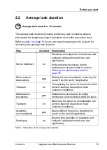
Страница 19: ...ance are described in section Starting the maintenance task on page 73 Rack removal disassembly yes Making the server available removing the server from the rack if applicable Transport no Transporting the server to the service table where required depends on local customer conditions Maintenance procedures yes Maintenance procedures including preliminary and concluding software tasks Transport no...

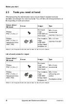
Страница 20: ...D SSD x4 front bezel M3 x 6 mm countersink C26192 Y10 C111 Phillips PH2 No 2 hexagonal cross SW5 PZ2 Fan modules cage HDD SSD bridge board Midplane kit M3 x 4 5 mm C26192 Y10 C67 Table 2 List of required tools and used screws for the 2 5 inch chassis Screw driver Bit insert Screw Usage Type Phillips PH2 No 2 Enclosure cover HDD SSD x4 front bezel M3 x 6 mm countersink Phillips PH2 No 2 hexagonal c...

Страница 21: ...tenance task ensure that all required manuals are available according to the overview below I Ensure to store all printed manuals enclosed with your server in a save place for future reference Unless stated otherwise all manuals are available online at http manuals ts fujitsu com under Industry standard servers For Japan http www fujitsu com jp products computing servers primergy manual ...

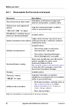
Страница 22: ...n Available online ServerView Suite Local Service Concept LSC user guide ServerView Operations Manager Server Management user guide Illustrated Spares catalog Spare parts identification and information system available for online use or download Windows OS at http manuals ts fujitsu com illustrated_spares or from the CSS component view of the ServerView Operations Manager Glossary Available online...

Страница 23: ...d Maintenance Manual 23 Before you start Third party documentation Operating system documentation online help Peripherals documentation Document Description Table 4 Documentation you need at hand for the server enclosure ...

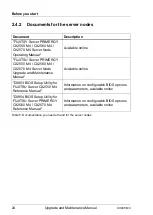
Страница 24: ... M4 CX2560 M4 CX2570 M4 Server Node Upgrade and Maintenance Manual Available online D3853 BIOS Setup Utility for FUJITSU Server CX2550 M4 Reference Manual Information on configurable BIOS options and parameters available online D3854 BIOS Setup Utility for FUJITSU Server PRIMERGY CX2560 M4 CX2570 M4 Reference Manual Information on configurable BIOS options and parameters available online Table 5 D...

Страница 25: ...e contact your sales outlet or our customer service team The actions described in this manual shall be performed by technical specialists A technical specialist is a person who is trained to install the server enclosure including hardware and software Repairs to the server enclosure that do not relate to CSS failures shall be performed by service personnel Please note that unauthorized interferenc...

Страница 26: ...ease to 40 C If the server enclosure is integrated into an installation that draws power from an industrial power supply network with an IEC309 connector the power supply s fuse protection must comply with the requirements for non industrial power supply networks for type A connectors The server enclosure automatically adjusts itself to a mains voltage see the type label of your server enclosure E...

Страница 27: ...e relevant instructions in this manual Never connect or disconnect data transmission lines during a storm risk of lightning hazard Make sure that no objects e g jewelry paperclips etc or liquids can get inside the server enclosure risk of electric shock short circuit In emergencies e g damaged casing controls or cables penetration of liquids or foreign bodies contact the server enclosure administr...

Страница 28: ...hutdown before installing or removing internal options Do not damage or modify internal cables or internal devices Doing so may cause a server enclosure failure fire or electric shock and will void the warranty and exempt the manufacturer from all liability The circuit boards and soldered parts of internal options are exposed and can be damaged by static electricity To ensure reliable protection y...

Страница 29: ...Cd Cadmium Hg Mercury Pb Lead Working with optical disk drives and media When working with optical disk drives these instructions must be followed V CAUTION Only use CDs DVDs BDs that are in perfect condition in order to prevent data loss equipment damage and injury Check each CD DVD BD for damage cracks breakages etc before inserting it in the drive Note that any additional labels applied may cha...

Страница 30: ...ng from the center to the edge Do not use benzene thinners water record sprays antistatic agents or silicone impregnated cloth Be careful not to damage the CD DVD BD surface Keep the CDs DVDs BDs away from heat sources Do not bend or place heavy objects on CDs DVDs BDs Do not write with ballpoint pen or pencil on the label printed side Do not attach stickers or similar to the label side Doing so m...

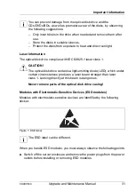
Страница 31: ...aser class 1 V CAUTION The optical disk drive contains a light emitting diode LED which under certain circumstances produces a laser beam stronger than laser class 1 Looking directly at this beam is dangerous Never remove parts of the optical disk drive casing Modules with Electrostatic Sensitive Devices ESD modules Modules with electrostatic sensitive devices are identified by the following stick...

Страница 32: ...on of how to handle ESD modules see the relevant European or international standards EN 61340 5 1 ANSI ESD S20 20 Transporting the server enclosure V CAUTION Only transport the server enclosure in its original packaging or in packaging that protects it from impacts and jolts In Japan and APAC transporting the server enclosure in its original packaging does not apply Do not unpack the server enclos...

Страница 33: ...fety information of the rack and the warning label If the server enclosure rack is intended for permanent connection to the mains only an authorized specialist electrician is allowed to work Please follow the regulation of each country If the server enclosure is integrated into an installation that draws power from an industrial power supply network with an IEC309 type connector the power supply s...

Страница 34: ... reading out measurement values including those relating to current energy consumption and air temperatures Either the Performance Monitor or the Task Manager can be used to read out CPU utilization levels The system complies with the requirements of European Regulations Find the CE declaration on certificate portal https sp ts fujitsu com sites certificates default aspx To open the CE declaration...

Страница 35: ...itched on should be switched off until they are needed as well as during long breaks and after completion of work Packaging information This packaging information does not apply in Japan and APAC Do not throw away the packaging You may need it later for transporting the server enclosure If possible the equipment should only be transported in its original packaging Information on handling consumabl...

Страница 36: ...consumables within Europe can also be found in the Returning used devices manual via your local Fujitsu branch or at http ts fujitsu com recycling The device must not be disposed of with domestic waste This device is labeled in compliance with European directive 2012 19 EU on waste electrical and electronic equipment WEEE This directive sets the framework for returning and recycling used equipment...

Страница 37: ...ify the required spare part and obtain technical data and order information Illustrated Spares catalogs are available online at http manuals ts fujitsu com illustrated_spares I In Japan the Fujitsu Illustrated Spares Catalog is not used Perform the following diagnostics procedures to identify defective servers and components 4 1 1 Locating the defective server When working in a datacenter environm...

Страница 38: ...rols and indicators on page 183 indicate if the defective component is a customer replaceable unit or if maintenance personnel needs to be dispatched to replace the part I The indicators also light up in standby mode and after a server restart due to a power failure 4 1 2 1 Customer Self Service CSS indicator Ê Check the CSS indicator on the front panel of the server enclosure or rear connectors p...

Страница 39: ...to the ServerView System Monitor user guide 4 1 3 Locating the defective component After determining the error class by the CSS or Global Error indicators see section Determining the error class on page 38 local diagnostic indicators on the system board HDD modules and PSUs only slide in units allow you to identify the defective component I For further information refer to the ServerView Suite Loc...

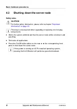
Страница 40: ...step is only required when upgrading or replacing non hot plug components Ê Inform the system administrator that the server node will be shut down and put offline Ê Terminate all applications Ê Press the On Off button either on the rear or on the corresponding front panel to shut down the server node I If the system is running an ACPI compliant operating system pressing the On Off button will perf...

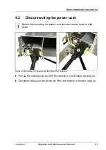
Страница 41: ...he power cord I Before disconnecting the power cord all server nodes must be shut down Figure 2 Removing the power cord from the PSU cable tie Ê Pull out the locking lever on the PSU cable tie 1 and loosen the loop 2 Ê Disconnect the power cord from the PSU and remove it from the cable tie ...

Страница 42: ...ortant information on page 25 I In most cases maintenance tasks can be performed while the server is extended from the rack However depending on accessibility or security guidelines it may make sense to completely remove the server from the rack cabinet for maintenance purposes 4 4 1 Preliminary steps Ê Shutting down the server node on page 40 Ê Disconnecting the power cord on page 41 Ê If applica...

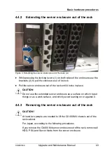
Страница 43: ...rver enclosure out of the rack until it locks in place V CAUTION Do not use the extended server enclosure as a surface on which to put things or as a work surface and strictly avoid leaning on or against it 4 4 3 Removing the server enclosure out of the rack V CAUTION At least two people are needed to lift the CX400 M4 chassis out of the rack cabinet For Japan according to the following procedures...

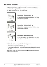
Страница 44: ...an 50 kg The server weighs more than 21 kg and is installed above the height of 25 U When using a lifter this removal procedure needs to be carried out by maintenance personnel For configurations below 32 kg At least two people are needed to lift the server out of the rack cabinet For configurations below 55 kg At least three people are needed to lift the server out of the rack cabinet For configu...

Страница 45: ...he rack A Ê Pull the server enclosure out of the rack as far as it will go 1 Ê Release the locking springs on both rack rails 2 Figure 5 Remove the server enclosure out of the rack B Ê Pull out the chassis from the outer rails I Remove the server enclosure from the rack carefully Must be done with at least two people ...

Страница 46: ...ode for example In the meantime all remaining server nodes run in throttling mode with reduced performance 4 5 1 Removing the CX2550 M4 CX2560 M4 server node V CAUTION Shut down the server node and disconnect all external cables Follow the safety instructions in the chapter Important information on page 25 Ê Remove the gasket of the lower server node and keep it for later use Ê Undo the locking me...

Страница 47: ... V CAUTION If the server node is difficult to pull out of the bay push the server node and then pull the server node while pushing the server node to the left side Figure 6 Removing the CX2550 M4 CX2560 M4 server node Ê Install the gasket of the lower server node again ...

Страница 48: ...structions in the chapter Important information on page 25 Figure 7 Removing the CX2570 M4 server node Ê Undo the locking mechanism 1 of the release lever and pull the server node out of the bay 2 V CAUTION If the server node is difficult to pull out of the bay push the server node and then pull the server node while pushing the server node to the left side Figure 8 Removing the CX2570 M4 server n...

Страница 49: ... open for a limited time in case of repairing a server node for example In the meantime all remaining server nodes run in throttling mode with reduced performance V CAUTION Follow the safety instructions in the chapter Important information on page 25 Figure 9 Removing the server node dummy module Ê Undo the locking mechanism 1 of the release lever and pull the server node dummy module out of the ...

Страница 50: ...and all peripheral devices Also unplug all power cables from the outlet Failure to do so can cause electric shock For further safety information please refer to chapter Important information on page 25 4 7 1 Opening the fan cover Figure 10 Removing the fan cover from the chassis Ê Shift the locking tab in the direction of the arrow 1 Ê Fold up the fan cover 2 and remove it 3 ...

Страница 51: ...cover is removed as described in section Opening the fan cover on page 50 Ê Remove five screws from the midplane cover see circles Ê Remove the midplane cover 4 8 Closing the server enclosure V CAUTION Before attaching the covers make sure no unnecessary parts or tools are left inside the server For further safety information please refer to chapter Important information on page 25 ...

Страница 52: ...ntenance Manual CX400 M4 Basic hardware procedures 4 8 1 Installing the midplane cover Figure 12 Installing the midplane cover on the chassis Ê Place the midplane cover as shown and secure it with five screws see circles ...

Страница 53: ...chassis Ê Insert the fan cover as shown 1 Ê Shift the locking tab in the direction of the arrow 2 and flip down the cover 3 Ê Shift the locking tab against the direction of the arrow 2 to secure the fan cover V CAUTION If the locking tab is stopped on the way to securing the fan cover shift the locking tab by finger into the locking position ...

Страница 54: ...rver node dummy module V CAUTION Follow the safety instructions in the chapter Important information on page 25 Figure 14 Installing the server node dummy module Ê Carefully push the server node dummy module at the handle into the server enclosure until the locking mechanism snaps into place ...

Страница 55: ...g Figure 15 CX400 M4 server node and PSU bay numbering rear view Population rules for server nodes CX2550 M4 I Not used bays must be equipped with server node dummy modules A PSU 1 B PSU 2 1 Server node bay 1 2 Server node bay 2 3 Server node bay 3 4 Server node bay 4 Number of nodes Bay 1 Bay 2 Bay 3 Bay 4 1 1 2 1 2 3 1 3 2 4 1 3 2 4 Table 6 CX2550 M4 population rules B A 3 1 2 4 ...

Страница 56: ...quipped with server node dummy modules Population rules for server nodes CX2570 M4 I Not used bays must be equipped with server node dummy modules Number of nodes Bay 1 Bay 2 Bay 3 Bay 4 1 1 2 1 2 3 1 3 2 4 1 3 2 4 Table 7 CX2560 M4 population rules Number of nodes Bay 1 Bay 2 Bay 3 Bay 4 1 1 1 2 1 1 2 2 Table 8 CX2570 M4 population rules ...

Страница 57: ...rocedures Population rules for server node mixing configuration CX2560 M4 CX2570 M4 Figure 16 CX400 M4 server node mixing I Not used bays must be equipped with server node dummy modules PSU PSU CX2570 M4 CX2560 M4 CX2560 M4 PSU PSU CX2570 M4 CX2560 M4 CX2560 M4 ...

Страница 58: ...ge 25 Ê Push the server node at the handle into the server enclosure until the locking mechanism snaps into place Ê If applicable connect all external cables to the server node Ê Remove the gasket of the lower server node and keep it for later use Ê Push the server node at the handle into the server enclosure until the locking mechanism snaps into place Ê Install the gasket of the lower server nod...

Страница 59: ...tenance Manual 59 Basic hardware procedures V CAUTION When connecting and removing the tubes from the node check that the LC flexible tubes riser is not off as shown This is the good case This is the bad case the bracket is off ...

Страница 60: ...ver node V CAUTION Follow the safety instructions in the chapter Important information on page 25 Figure 17 Installing the server node Ê Push the server node at the handle into the server enclosure until the locking mechanism snaps into place Ê If applicable connect all external cables to the server node ...

Страница 61: ... enclosure in the rack 4 11 1 Removing the inner rail from the carrier rails Ê Identify the inner rail and the outer rail Figure 18 Inner 2 and outer rail 1 Figure 19 Starting position of inner and outer rail Ê Push the lever 1 and pull the inner rail as far as possible towards the front side 2 ...

Страница 62: ...es Figure 20 Turning outer rail Ê Turn the rails to the other side see arrow Figure 21 Removing inner rail from outer rail Ê Push the locking latch 1 and pull the outer rail as far as possible towards the front side 2 Now the inner rail is removed from the outer rail ...

Страница 63: ...rail Ê Move the right carrier rail towards the server enclosure and position the holes onto the positioning screws 1 The carrier rail must lock in the corresponding hole Ê Push the carrier rail towards the front side until it locks into the supporting holes nicely 2 Figure 23 Adjusting the carrier rail Ê Fasten the carrier rail with two M4 screws 3 Ê Repeat this procedure to install the left carri...

Страница 64: ...rack Ê Mark the position of the bottom edge of the server enclosure on the support uprights Ê Identify the right and the left rail Figure 24 Attaching the left carrier rail Figure 25 Adjusting the positioning clip Ê Move the left carrier rail towards the rear side 2 while holding the positioning clip 1 The mounting aid must lock in the corresponding hole ...

Страница 65: ... The mounting aid must lock in the corresponding hole Ê Release the positioning clip 5 after the designated position is reached Figure 26 Tightening the M5 screw Ê Tighten the M5 screw 6 on the front side of the rail Ê Repeat this procedure to install the right rail 4 11 4 Lift the server into the rack cabinet V CAUTION At least two people are needed to position the server on the rack rails For Ja...

Страница 66: ...he height of 25 U When using a lifter this installation procedure needs to be carried out by maintenance personnel For configurations below 32 kg At least two people are needed to lift the server into the rack cabinet For configurations below 55 kg At least three people are needed to lift the server into the rack cabinet For configurations above 55 kg At least four people are needed to lift the se...

Страница 67: ...ded to position the server on the rack rails Figure 27 Mounting the server enclosure into the rack A Ê Set the back end of both inner rails 1 into the front entry of the both outer rails 2 Figure 28 Mounting the server enclosure into the rack A Ê Push the server as far as possible into the rack 1 2 ...

Страница 68: ...e 29 Mount the server enclosure in the rack B Ê When the server enclosure is stopped push the locking latch 1 on both sides and push the server in the rack 2 Figure 30 Mounting the server into the rack C Ê Push the enclosure into the rack 1 until the locking mechanism engages ...

Страница 69: ...A Figure 31 Installing the CMA A Ê Slide the CMA connector outer rail onto the end of the outer rail of the rack mounting kit until it clicks into place see arrow Figure 32 Installing the CMA B Ê Slide the CMA connector inner rail onto the end of the inner rail of the rack mounting kit until it clicks into place ...

Страница 70: ...al CX400 M4 Basic hardware procedures Figure 33 Installing the CMA C Ê Slide the CMA connector on the opposite side onto the end of the outer rail of the rack mounting kit until it clicks into place see arrow Figure 34 CMA installed ...

Страница 71: ... true phase redundancy the second PSU should be connected to a different AC power source from the other PSU If one AC power source should fail the server will still continue to run Ê Connect the power cords to the PSUs Ê Ensure that the status indicator on the PSU is lit green see section Indicator on hot plug PSU on page 192 Figure 35 Example Locking the cable clamp of a PSU Ê Loop the cable tie ...

Страница 72: ...CX2560 M4 CX2570 M4 Ê If applicable connect all external cables to the server node Figure 36 Controls and indicators of the server node Ê Press the On Off button either on the rear or on the corresponding front panel to start up the server node The power on indicator is lit green and the ID indicator is off I For more information refer to section Indicators on the front panel node related on page ...

Страница 73: ...iRMC user guides Using the ID button on the front panel Ê Press the ID button on the front panel to switch on the system identification LEDs I For more information see section Controls and indicators on the front of the server enclosure on page 183 Using the ID icon in the iRMC web interface Ê Log in to the iRMC S5 web interface The icon that represents the ID indicator LED resides on the right of...

Страница 74: ...cal Service Concept LSC and iRMC S5 Web Interface user guides Using the ID button on the front panel Ê Press the ID button on the front panel to switch off the ID indicators Using the ID icon in the RMC web interface Ê Log in to the iRMC S5 web interface The icon that represents the ID indicator LED resides on the right of the menu bar Its color symbolizes its status blue the ID LED is on grey the...

Страница 75: ...m Event Log SEL on page 77 to verify whether the backup data on the Chassis ID EPROM has been restored to the system board Chassis IDPROM Restore successful After replacing the Chassis ID EPROM I In case of the PRIMERGY CX400 M4 server enclosure the Chassis ID EPROM is integrated on the chassis interface board in the midplane kit Ê Check the SEL log files as described in section Viewing and cleari...

Страница 76: ...on like server name and model housing type serial number and manufacturing data are stored in the chassis interface board In order to integrate your system into the ServerView management environment and to enable server installation using the ServerView Installation Manager system data needs to be complete and correct After replacing the midplane kit system information has to be entered using the ...

Страница 77: ...ts I Note on the Driver Monitor of the ServerView Operations Manager The Driver Monitor view gives you an overview of the monitored components as well as the associated events contained in the system event log on the managed server Under Monitored Components the monitored components are listed If a component has the status Warning or Error you can select it in the list and click Acknowledge This c...

Страница 78: ...r field Ê You can also filter the table using the filter lists in the header of some columns I For more information on iRMC settings see the iRMC user guides 5 2 5 2 Clearing the SEL You can clear the System Event Log SEL using the ServerView iRMC web interface Ê Log in to the ServerView iRMC web interface Ê Open the Logs menu Ê Click System Event Log to open the System Event Log page All events c...

Страница 79: ...en the Cooling page Ê Expand the Cooling Devices group Ê Click Start Fan Test I For more information on iRMC settings see the iRMC user guides Executing the fan test via ServerView Operations Manager Ê Open the ServerView Operations Manager and log in Ê Under Administration select Server Configuration Ê In the hierarchy tree of the Server list tab select the server to be configured Ê In the right ...

Страница 80: ...follow the instructions provided separately 5 2 7 Updating ServerView RAID Manager For the spare parts of the product compatible parts equal to the original parts might be used If an old version of the ServerView RAID Manager is used the SSD life monitoring function does not work correctly after replacement Please always use the latest version of the ServerView RAID Manager http ts fujitsu com sup...

Страница 81: ...hen removing the PSU Doing so may cause electric shock If the PSU is hard to remove do not pull out it by force The PSU is heavy so handle it carefully If you drop it by mistake injuries may result Follow the safety instructions in the chapter Important information on page 25 6 1 Basic information The system has two bays for hot plug PSUs The server enclosure uses two hot plug PSU which automatica...

Страница 82: ... 38 Population rules for the hot plug PSUs Both hot plug PSUs must be of the same type The PSU dummy module is installed in the hot plug PSU bay 2 top for non redundant configuration In a non redundant configuration only a 2400 W PSU can be installed 1 hot plug PSU bay 1 bottom 2 hot plug PSU bay 2 top ...

Страница 83: ...PSU is defective A hot plug PSU is defective when the indicator on the hot plug PSU lights up orange I For more information see section Indicator on hot plug PSU on page 192 Ê Shutting down the server node on page 40 non redundancy Ê Disconnect the power cord from the defective hot plug PSU as described in Disconnecting the power cord on page 41 The power supply of the server node need not be turn...

Страница 84: ...f the hot plug PSU halfway upward in the direction of the arrow 1 Ê Push the lock in direction of the arrow 2 Ê Grip the handle and pull out the hot plug PSU in the direction of the arrow 3 V CAUTION Never leave the bay for the hot plug PSU empty for more than two minutes during operation Otherwise excessive temperatures could damage system components ...

Страница 85: ...alling the hot plug PSU Figure 40 Folding up the handle Ê Push the handle of the hot plug PSU in the direction of the arrow Figure 41 Installing the hot plug PSU Ê Carefully push the hot plug PSU into the empty bay 1 until it stops Ê Flip the handle of the hot plug PSU down 2 ...

Страница 86: ...s locked in position This is the only way to prevent the PSU from sliding out of its bay and being damaged during transportation 6 2 4 Concluding steps Perform the following procedures Ê Connecting the power cord on page 71 Ê Only when replacing a hot plug PSU in a non redundant configuration Switching on the server node s on page 72 ...

Страница 87: ... during operation Otherwise excessive temperatures could damage system components 6 3 1 Removing the PSU dummy module Figure 42 Removing the PSU dummy module Ê Press the handles of the PSU dummy module in the direction of the arrows 1 Ê Pull the PSU dummy module out of the bay 2 Customer Replaceable Unit CRU Hardware 5 minutes Tools Preliminary and concluding steps tool less Main steps tool less ...

Страница 88: ... Power supply unit PSU 6 3 2 Installing the PSU dummy module Figure 43 Installing the PSU dummy module Ê Press the handles of the PSU dummy module in the direction of the arrows 1 Ê Push the PSU dummy module into the empty bay 1 until it stops ...

Страница 89: ...t noise may be audible for a short while This does not indicate a failure Depending on the OS you can configure the write cache settings for the HDDs If a power failure should occur while the write cache is enabled cached data may be lost When disposing of transferring or returning a HDD or SSD wipe out the data on the drive for your own security Rough handling of HDDs may damage the stored data T...

Страница 90: ...SATA backplane wirelessly This allows HDD SSD modules to be plugged in or pulled out easily Six SATA HDDs SSDs can be controlled by the onboard SATA controller To control SAS HDDs SSDs an additional SAS RAID controller must be installed Hybrid configurations of SAS HDDs SATA HDDs SAS SSDs and SATA SSDs within the same logical drive RAID array are not supported If the server node has the correspond...

Страница 91: ...HDD SSD install order HDD SSD bays assignment Up to six HDDs SSDs are installed in a cage The cages are assigned to the server nodes as follows CX400 M4 equipped with CX2550 M4 server nodes PSU 2 Node 4 Node 2 PSU 1 Node 3 Node 1 Server nodes and PSUs rear view 0 1 0 1 0 1 0 1 Node 1 Node 2 Node 3 Node 4 HDD SSD cages and front panel front view CX400 M4 equipped with CX2560 M4 server nodes PSU 2 N...

Страница 92: ...is backplane is used with CX2560 M4 and CX2570 M4 server nodes HDD backplane 1 2 provides 2 SATA connectors 1 2 This backplane is used with CX2550 M4 server nodes The following figures shows how the cages depending of the installed backplanes can be equipped CX400 M4 equipped with CX2570 M4 server nodes PSU 2 Node 3 Node 1 PSU 1 Server nodes and PSUs rear view 0 1 2 3 4 5 0 1 2 3 4 5 Node 1 Node 3...

Страница 93: ... M4 Upgrade and Maintenance Manual 93 Hard disk drives HDD solid state drives SSD and 2 5 inch PCIe SSD Type A HDD SSD backplane 1 1 Type B HDD SSD backplane 1 2 SAS SATA SAS SATA PCIe SFF SSD combi SATA 0 0 ...

Страница 94: ...ate drives SSD and 2 5 inch PCIe SSD 7 1 4 HDD SSD cage bezels There are two different bezels to cover unused HDD SSD cages or unused HDD SSD respectively HDD SSD6x front bezel HDD SSD4x front bezel only for CX2550 M4 Instead four HDD SSD dummy modules can also be installed ...

Страница 95: ...SSD 7 2 Installing 2 5 inch HDD SSD modules 7 2 1 Preliminary steps Perform the following procedures Ê Locate the correct drive bay as described in section HDD SSD install order on page 91 Customer Replaceable Unit CRU Hardware 5 minutes Tools Preliminary and concluding steps tool less Main steps tool less ...

Страница 96: ...HDD SSD bays Before installing an additional HDD SSD the dummy module needs to be removed from the desired drive bay Ê Press in on the locking clips of the dummy module to disengage the locking mechanism Ê While keeping the locking clip pressed pull the dummy module out of its bay V CAUTION Save the dummy module for future use Always replace dummy modules into unused HDD SSD bays to comply with ap...

Страница 97: ... a 2 5 inch HDD SSD module Figure 45 Installing the 2 5 inch HDD SSD module Ê Insert the HDD SSD module into a drive bay and carefully push back as far as it will go 1 Ê Close the release lever in the direction of the arrow 2 7 2 4 Concluding steps Perform the following procedures Ê Performing a RAID array rebuild on page 75 ...

Страница 98: ...rive is part of a RAID array you first need to delete the array using ServerView RAID Manager V CAUTION All data on all HDDs SSDs in the array will be lost when deleting the array Be sure to back up your data before deleting a RAID array I For further information please refer to the ServerView Suite RAID Management user guide available online at http manuals ts fujitsu com Customer Replaceable Uni...

Страница 99: ...id state drives SSD and 2 5 inch PCIe SSD 7 3 2 Removing a 2 5 inch HDD SSD module Figure 46 Removing a 2 5 inch HDD SSD module Ê Undo the locking mechanism of the release lever 1 Ê Swing the release lever in the direction of the arrow 2 Ê Pull out the HDD SSD module 3 ...

Страница 100: ...D dummy module V CAUTION If the removed HDD SSD module is not replaced immediately always replace the HDD SSD dummy module into the unused HDD SSD bay to comply with applicable EMC regulations and satisfy cooling requirements Figure 47 Installing a 2 5 inch HDD SSD dummy module Ê Slide the dummy module into the drive bay until it locks in place ...

Страница 101: ...AID RAID levels 0 1 10 5 and 50 are supported for internal HDD configurations Modular RAID 5 6 controller with MegaRAID functionality MegaRAID RAID levels 0 1 10 5 50 6 and 60 are supported for internal HDD configurations As an option a flash backup unit FBU can save the memory content even if the power fails Cache memory size of up to 8 GB is available RAID configuration without a RAID controller...

Страница 102: ... software 7 4 2 Removing a 2 5 inch HDD SSD module Ê Remove the HDD SSD module to be replaced from the server as described in section Removing a 2 5 inch HDD SSD module on page 99 7 4 3 Installing a 2 5 inch HDD SSD module Ê Install the new HDD SSD module into the empty drive bay as described in section Installing 2 5 inch HDD SSD modules on page 95 7 4 4 Concluding steps Perform the following pro...

Страница 103: ...e 40 Ê Disconnecting the power cord on page 41 Ê Remove all HDD SSD modules from the relevant HDD SSD cage as described in section Removing 2 5 inch HDD SSD modules on page 98 Ê Extending the server enclosure out of the rack on page 43 Ê Opening the server enclosure on page 50 Ê Remove the fan modules as described in section Removing the fan module on page 131 Field Replaceable Unit FRU Hardware 1...

Страница 104: ... 2 5 inch PCIe SSD 7 5 2 Removing the fan modules cage Figure 48 Disconnecting the fan cables from the midplane Ê Disconnect the fan cables from the midplane see circles Figure 49 Removing the fan modules cage Ê Remove four screws see circles Ê Lift the fan modules cage out of the enclosure 1 ...

Страница 105: ...105 Hard disk drives HDD solid state drives SSD and 2 5 inch PCIe SSD 7 5 3 Removing the 2 5 inch HDD SSD backplane Figure 50 Removing the HDD SSD backplane Ê Carefully pull up on the backplane in a vertical motion and remove it from its slot ...

Страница 106: ...talling the 2 5 inch HDD SSD backplane Figure 51 Installing the HDD SSD backplane Ê Carefully insert the backplane into the desired slot 1 and press down in a vertical motion until it is fully seated in the slot 2 Make sure that the hooks of the backplane bracket are inserted in the recesses of the enclosure see circles ...

Страница 107: ...ules cage Figure 52 Inserting the fan modules cage Ê Carefully insert the fan modules cage in the enclosure 1 Ê Secure the fan modules cage with four screws see circles V CAUTION Ê Secure the fan modules cage with four screws while pushing the fan modules cage so that the edge of the fan modules cage is lower than the edge of the chassis ...

Страница 108: ...grade and Maintenance Manual CX400 M4 Hard disk drives HDD solid state drives SSD and 2 5 inch PCIe SSD Figure 53 Connecting the fan cables to the midplane Ê Connect the fan cables to the midplane see circles ...

Страница 109: ...long cables A and the short cables B to the corresponding midplane connectors Ê Arrange the cables so that the cables are lower than the fan cage Ê After finishing the cable arrangement check that the cables do not touch the capacitor on the midplane board If the cables touch the capacitor on the midplane board rearrange the cables ...

Страница 110: ...e fan modules as described in section Installing the fan module on page 133 Ê Closing the server enclosure on page 51 Ê Mounting the server enclosure in the rack on page 61 Ê Install all HDD SSD modules into the relevant cage as described in section Installing 2 5 inch HDD SSD modules on page 95 Ê Connecting the power cord on page 71 Ê Switching on the server node s on page 72 ...

Страница 111: ...ng procedures Ê Shut down the server nodes as described in section Shutting down the server node on page 40 Ê Disconnecting the power cord on page 41 Ê Removing server nodes from the server enclosure on page 46 Ê Removing the hot plug PSU on page 84 Ê Extending the server enclosure out of the rack on page 43 Ê Opening the server enclosure on page 50 Ê Remove all fan modules as described in section...

Страница 112: ...stalling the HDD SSD bridge board Figure 54 Installing the HDD SSD bridge board Ê At a slight angle lower the HDD SSD bridge board into the chassis Ê Carefully shift the HDD SSD bridge board towards the left 1 until the shoulder screw caps on the chassis engage with the recesses of the HDD SSD bridge board see circles ...

Страница 113: ...Perform the following procedures Ê Installing the midplane kit on page 153 Ê Install all HDD SSD backplanes as described in section Installing the 2 5 inch HDD SSD backplane on page 106 Ê Installing the fan modules cage on page 107 Ê Install all fan modules as described in section Installing the fan module on page 133 Ê Closing the server enclosure on page 51 Ê Mounting the server enclosure in the...

Страница 114: ...ection Removing 2 5 inch HDD SSD modules on page 98 Ê Extending the server enclosure out of the rack on page 43 Ê Opening the server enclosure on page 50 Ê Remove all fan modules as described in section Removing the fan module on page 131 Ê Removing the fan modules cage on page 104 Ê Remove all HDD SSD backplanes as described in section Removing the 2 5 inch HDD SSD backplane on page 105 Ê Removin...

Страница 115: ...the HDD SSD bridge board Figure 56 Removing the HDD SSD bridge board Ê Carefully shift the HDD SSD bridge board in the direction of the arrow 1 until the shoulder screw caps on the chassis will rest in the wide ends of the keyhole slots on the HDD SSD bridge board see circles Ê Fold up the HDD SSD bridge board 2 and remove it ...

Страница 116: ...stalling the HDD SSD bridge board Figure 57 Installing the HDD SSD bridge board Ê At a slight angle lower the HDD SSD bridge board into the chassis Ê Carefully shift the HDD SSD bridge board towards the left 1 until the shoulder screw caps on the chassis engage with the recesses of the HDD SSD bridge board see circles ...

Страница 117: ...Perform the following procedures Ê Installing the midplane kit on page 153 Ê Install all HDD SSD backplanes as described in section Installing the 2 5 inch HDD SSD backplane on page 106 Ê Installing the fan modules cage on page 107 Ê Install all fan modules as described in section Installing the fan module on page 133 Ê Closing the server enclosure on page 51 Ê Mounting the server enclosure in the...

Страница 118: ...icable shut down the relevant server node as described in section Shutting down the server node on page 40 Ê Disconnecting the power cord on page 41 Ê If applicable remove all HDD SSD modules from the relevant HDD SSD cage as described in section Removing 2 5 inch HDD SSD modules on page 98 Customer Replaceable Unit CRU Hardware 5 minutes Tools Preliminary and concluding steps tool less Main steps...

Страница 119: ... Hard disk drives HDD solid state drives SSD and 2 5 inch PCIe SSD 7 8 2 Removing the HDD SSD x6 front bezel Figure 59 Removing the HDD SSD x6 front bezel Ê Grasp behind the handle edge at a lower corner of the bezel and remove it from the cage ...

Страница 120: ...SSD 7 8 3 Removing the HDD SSD x6 front bezel screw type Figure 60 Removing the front bezel fixing screw Ê Remove the screw from the top of the chassis see circle Figure 61 Removing the HDD SSD x6 front bezel scew type Ê Grasp behind the handle edge at a lower corner of the bezel and remove it from the cage ...

Страница 121: ...drives SSD and 2 5 inch PCIe SSD 7 8 4 Removing the HDD SSD x4 front bezel Figure 62 Removing the front bezel fixing screw Ê Remove the screw from the top of the chassis see circle Figure 63 Removing the HDD SSD x4 front bezel Ê Grasp behind the bezel and remove it from the cage ...

Страница 122: ... Figure 64 Installing the HDD SSD x6 front bezel Ê Insert the bezel in front of the empty slot with the bendings of the bezel pointing downwards 7 8 6 Installing the HDD SSD x6 front bezel screw type Figure 65 Installing the HDD SSD x6 front bezel screw type Ê Insert the bezel in front of the empty slot with the bendings of the bezel pointing downwards ...

Страница 123: ...4 Upgrade and Maintenance Manual 123 Hard disk drives HDD solid state drives SSD and 2 5 inch PCIe SSD Figure 66 Removing the front bezel fixing screw Ê Remove the screw from the top of the chassis see circle ...

Страница 124: ...lling the HDD SSD x4 front bezel Ê If applicable remove the HDD SSD modules beside the front bezel see Removing a 2 5 inch HDD SSD module on page 99 Figure 67 Installing the HDD SSD x4 front bezel Ê Insert the bezel in front of the empty cage The guide pin on the upper edge of the bezel 1 must be in the recess of the cage ...

Страница 125: ...h one screw from top of chassis see circle 7 8 8 Concluding steps Perform the following procedures Ê If applicable install the HDD SSD modules you removed before as described in section Installing 2 5 inch HDD SSD modules on page 95 Ê Connecting the power cord on page 71 Ê If applicable switch on the relevant server node as described in section Switching on the server node s on page 72 ...

Страница 126: ...126 Upgrade and Maintenance Manual CX400 M4 Hard disk drives HDD solid state drives SSD and 2 5 inch PCIe SSD ...

Страница 127: ... internal options Circuit boards and soldered parts of internal options are exposed and can be damaged by static electricity Always discharge static build up e g by touching a grounded object before handling electrostatic sensitive devices ESDs Do not touch the circuitry on boards or soldered parts Hold circuit boards by their metallic areas or edges If devices are installed or disassembled using ...

Страница 128: ...modules Fan positions The figure 69 shows the position of the system fans 1 to 8 Figure 69 Fan positions Fan cables Two fans each are connected to the midplane via one Y cable There are two types of fan cables a short and a long version The short version is used for fan modules 3 4 and 7 8 and the long version is used for fan modules 1 2 and 5 6 Front ...

Страница 129: ... Upgrade and Maintenance Manual 129 System fan module Figure 70 Fan cables A Fan cable short version 90mm B Fan cable long version 130mm 1 Connectors to the midplane 2 Connectors to the fan modules 1 1 1 1 2 2 ...

Страница 130: ...s described exemplarily 8 2 1 Preliminary steps Perform the following procedures Ê Extending the server enclosure out of the rack on page 43 Ê Opening the fan cover on page 50 Ê Locate the defective fan module using the diagnostic panel on the cover of the server enclosure see section Fan indicators on page 193 Field Replaceable Unit FRU Hardware 5 minutes Tools Preliminary and concluding steps Ph...

Страница 131: ...odule 1 Ê Lift up the cable and the connector from the gap between fan modules 1 and 3 Ê Disconnect the fan cable from the fan connector see arrows Ê Remove the fan module see arrow V CAUTION Don t touch the fan blade after the fan module was removed from the chassis because the fan blade does rotate by inertia ...

Страница 132: ...p the cable and the connector from the gap between fan modules 2 and 4 Ê Disconnect the fan cable from the fan connector see arrows Ê Remove fan module 2 see arrow V CAUTION Don t touch the fan blade after the fan module was removed from the chassis because the fan blade does rotate by inertia ...

Страница 133: ...fan module 1 Ê Carefully insert the fan module into the bay and press down firmly until it is fully seated in the bay 1 The fan mounts must engage in the supports see circles Ê Connect the fan cable to the fan module connector see arrows Ê Arrange the fan wires into the gap between fan modules 1 and 3 see oval ...

Страница 134: ... fan modules 1 and 3 see circle Ensure that the top edge of the fan connector is lower than the fan height Ê Arrange the fan wires and the connector of fan module 2 into the gap between fan modules 2 and 4 in the same way as with fan module 1 Ensure that the top edge of the connector is lower than the fan ...

Страница 135: ...nd Maintenance Manual 135 System fan module Ê Clip the fan cable into the hooks to secure it see circles Ê Arrange the fan connector and cables so that the fan connector and cables are lower than the fan and the fan cage ...

Страница 136: ...ch the fan blade after the fan module was removed from the chassis because the fan blade does rotate by inertia It is preferable to route the fan cable for fan module 2 next to the fan connector for fan module 1 Ê Arrange the fan cables so that the fan cables are inside the fan cage ...

Страница 137: ...CX400 M4 Upgrade and Maintenance Manual 137 System fan module Ê Arrange the fan cables so that the tape area for cables does fit into the cutout of the fan cage ...

Страница 138: ...odule 1 Ê Connect the fan cable to the fan module connector see arrows Ê Arrange the fan wires into the gap between fan modules 2 and 4 see oval Ê Arrange the fan wires and the connector of fan module 2 into the gap between fan modules 2 and 4 in the same way as with fan module 1 Ensure that the top edge of the connector is lower than the fan ...

Страница 139: ...nd Maintenance Manual 139 System fan module Ê Clip the fan cable into the hooks to secure it see circles Ê Arrange the fan connector and cables so that the fan connector and cables are lower than the fan and the fan cage ...

Страница 140: ... Maintenance Manual CX400 M4 System fan module Ê Arrange the fan cables so that the fan cables are inside the fan cage Ê Arrange the fan cables so that the tape area for cables does fit into the cutout of the fan cage ...

Страница 141: ...aintenance Manual 141 System fan module 8 2 4 Concluding steps Perform the following procedures Ê Installing the fan cover on page 53 Ê Mounting the server enclosure in the rack on page 61 Ê Performing a fan test on page 79 ...

Страница 142: ...le at first then plug out the fan module itself 8 3 1 Preliminary steps Perform the following procedures Ê Extending the server enclosure out of the rack on page 43 Ê Opening the server enclosure on page 50 Field Replaceable Unit FRU Hardware 10 minutes Tools Preliminary and concluding steps Phillips PH2 No 2 hexagonal cross SW5 PZ2 Main steps tool less ...

Страница 143: ...8 3 2 Disconnecting the fan cable Figure 71 Disconnecting the fan cable Ê Pull the fan cable out of the gaps next to the fans 1 Ê Disconnect the fans from the fan cable 2 Figure 72 Removing the fan module Ê Remove the fan module next to the midplane out of the bay ...

Страница 144: ...module Figure 73 Disconnecting the fan cable from the midplane Ê Unplug the fan cable from the midplane see circle 8 3 3 Connecting the fan cable Figure 74 Connecting the fan cable from the midplane Ê Plug the fan cable in the midplane connector see circle ...

Страница 145: ...ION Ê Arrange the cables so that the fan connector and cables are lower than the fan and the fan cage Ê Arrange the fan cables so that the fan cables are inside the fan cage Arrange the fan cables so that the tape area for cables does fit into the cutout of the fan cage ...

Страница 146: ... Carefully insert the fan module into the bay and press down firmly until it is fully seated in the bay The fan mounts must engage in the supports see circles Figure 76 Connecting the fan cable to the fan modules Ê Connect the fans to the fan cable 1 Ê Fold the cable into the gaps next to the fans 2 ...

Страница 147: ...ntenance Manual 147 System fan module Ê Arrange the fan connector and cables so that the fan connector and cables are lower than the fan and the fan cage Ê Arrange the fan cables so that the fan cables are inside the fan cage ...

Страница 148: ...odule 8 3 4 Concluding steps Perform the following procedures Ê Closing the server enclosure on page 51 Ê Mounting the server enclosure in the rack on page 61 Ê Arrange the fan cables so that the tape area for cables does fit into the cutout of the fan cage ...

Страница 149: ...ternal options Circuit boards and soldered parts of internal options are exposed and can be damaged by static electricity Always discharge static build up e g by touching a grounded object before handling electrostatic sensitive devices ESDs Do not touch the circuitry on boards or soldered parts Hold circuit boards by their metallic areas or edges If devices are installed or disassembled using met...

Страница 150: ... midplane kit variants depending on what type of nodes are installed in the enclosure Midplane 1 kit This midplane kit is used for CX2550 M4 CX2560 M4 and CX2570 M4 Figure 77 Midplane 1 kit components Midplane 2 kit Future use Pos Component 1 PSU interposer 2 Chassis interface board 3 Midplane ...

Страница 151: ...M to the Chassis ID EPROM After replacing the system board the backup data is restored from the Chassis ID board to the new system board 9 2 1 Preliminary steps Perform the following procedures Ê Shutting down the server node on page 40 Ê Disconnecting the power cord on page 41 Ê Removing server nodes from the server enclosure on page 46 Ê Removing the hot plug PSU on page 84 Ê Extending the serve...

Страница 152: ... kit 9 2 2 Removing the midplane kit Figure 78 Removing the midplane kit A Ê Unplug the front panel cables from the midplane 1 Ê Hang the cable ends on the housing edge to the outside Ê Remove two screws see circles Figure 79 Removing the midplane kit B ...

Страница 153: ...D SSD bridge board Ê Move the midplane kit about 5 cm to the front 3 and remove it in a vertical motion of the chassis 9 2 3 Installing the midplane kit Figure 80 Installing the midplane kit A Ê Lower the midplane kit in a vertical motion into the chassis as shown Ê Move the midplane kit in the direction of the arrows so that the guide pins see circles fit into the slots in the housing wall ...

Страница 154: ...stalling the midplane kit B Ê Press down the midplane firmly until it is fully seated in the slots of the HDD SSD bridge board Figure 82 Installing the midplane kit C Ê Secure the midplane kit with two screws see circles Ê Plug in the front panel cables to the midplane 1 ...

Страница 155: ...age 133 Ê Closing the server enclosure on page 51 Ê Mounting the server enclosure in the rack on page 61 Ê Installing the hot plug PSU on page 85 Ê Installing the server node in the server enclosure on page 55 Ê Connecting the power cord on page 71 Ê Switching on the server node s on page 72 Ê Verifying system information backup restore on page 75 Ê Using the Chassis ID Prom Tool on page 76 ...

Страница 156: ...156 Upgrade and Maintenance Manual CX400 M4 Midplane kit ...

Страница 157: ...s and soldered parts of internal options are exposed and can be damaged by static electricity Always discharge static build up e g by touching a grounded object before handling electrostatic sensitive devices ESDs Do not touch the circuitry on boards or soldered parts Hold circuit boards by their metallic areas or edges For further information please refer to chapter Important information on page ...

Страница 158: ...M4 enclosure has two front panels which contain the operating panels for the server nodes installed see section Server enclosure front on page 179 Each front panel is connected to the midplane by a cable Figure 83 Front panel cable 1 Connector to the front panel 2 Connector to the midplane ...

Страница 159: ...form the following procedures Ê Shutting down the server node on page 40 Ê Disconnecting the power cord on page 41 Ê Extending the server enclosure out of the rack on page 43 Field Replaceable Unit FRU Hardware 5 minutes Tools Preliminary and concluding steps tool less Main steps Phillips PH2 No 2 hexagonal cross SW5 PZ2 ...

Страница 160: ...160 Upgrade and Maintenance Manual CX400 M4 Front panel 10 2 2 Removing the front panel Figure 84 Loosen the front panel Ê Loosen the front panel by removing two screws see circles ...

Страница 161: ...CX400 M4 Upgrade and Maintenance Manual 161 Front panel Figure 85 Disconnecting the front panel Ê Unplug the front panel cable from the front panel see oval ...

Страница 162: ...162 Upgrade and Maintenance Manual CX400 M4 Front panel 10 2 3 Installing the front panel Figure 86 Connecting the front panel Ê Connect the front panel cable to the front panel see oval ...

Страница 163: ...curing the front panel Ê Secure the front panel with two screws see circles 10 2 4 Concluding steps Perform the following procedures Ê Mounting the server enclosure in the rack on page 61 Ê Connecting the power cord on page 71 Ê Switching on the server node s on page 72 ...

Страница 164: ...on page 40 Ê Disconnecting the power cord on page 41 Ê Extending the server enclosure out of the rack on page 43 10 3 2 Removing the front panel Figure 88 Loosen the front panel Ê Loosen the front panel by removing two screws see circles Field Replaceable Unit FRU Hardware 5 minutes Tools Preliminary and concluding steps tool less Main steps Phillips PH2 No 2 hexagonal cross SW5 PZ2 ...

Страница 165: ...CX400 M4 Upgrade and Maintenance Manual 165 Front panel Figure 89 Disconnecting the front panel Ê Unplug the front panel cable from the front panel see oval ...

Страница 166: ...X400 M4 Front panel 10 3 3 Installing the front panel Figure 90 Connecting the front panel Ê Connect the front panel cable to the front panel see oval Figure 91 Securing the front panel Ê Secure the front panel with two screws see circles ...

Страница 167: ...ntenance Manual 167 Front panel 10 3 4 Concluding steps Perform the following procedures Ê Mounting the server enclosure in the rack on page 61 Ê Connecting the power cord on page 71 Ê Switching on the server node s on page 72 ...

Страница 168: ...e on page 40 Ê Disconnecting the power cord on page 41 Ê Extending the server enclosure out of the rack on page 43 Ê Opening the server enclosure on page 50 Ê Removing the fan module on page 131 Ê Removing the fan modules cage on page 104 Field Replaceable Unit FRU Hardware 30 minutes Tools Preliminary and concluding steps tool less Main steps Phillips PH2 No 2 hexagonal cross SW5 PZ2 ...

Страница 169: ...t panel cable from the midplane Ê Unplug the front panel cable from the midplane see oval Ê Remove the cable from the cable guide see arrows Ê Remove the left front panel as described in section Removing the front panel on page 160 Figure 93 Removing the front panel cable Ê Carefully pull the front panel cable out of the cable duct ...

Страница 170: ...nt panel cable A Ê Carefully shift the front panel cable through the cable duct Ê Install the left front panel as described in section Installing the front panel on page 162 Figure 95 Installing the left front panel cable B Ê Connect the front panel cable to the midplane see oval Ê Insert the cable into the cable guide see arrows ...

Страница 171: ... Ê Installing the fan modules cage on page 107 Ê Install all fan modules as described in section Installing the fan module on page 133 Ê Closing the server enclosure on page 51 Ê Mounting the server enclosure in the rack on page 61 Ê Connecting the power cord on page 71 Ê Switching on the server node s on page 72 ...

Страница 172: ...ct all power cords as described in section Disconnecting the power cord on page 41 Ê Extending the server enclosure out of the rack on page 43 Ê Opening the server enclosure on page 50 Ê Remove the fan modules as described in section Removing the fan module on page 131 Ê Removing the fan modules cage on page 104 Field Replaceable Unit FRU Hardware 30 minutes Tools Preliminary and concluding steps ...

Страница 173: ...l cable out of the cable guide Ê Lift up the cable from the cable guide see arrows Ê Unplug the front panel cable from the midplane see circle Ê Remove the left right panel as described in section Removing the front panel on page 164 Figure 97 Removing the front panel cable Ê Carefully pull the front panel cable out of the cable duct ...

Страница 174: ... panel cable A Ê Carefully shift the front panel cable through the cable duct Ê Install the right front panel as described in section Installing the front panel on page 166 Figure 99 Installing the right front panel cable B Ê Connect the front panel cable to the midplane see circle Ê Insert the cable into the cable guide see arrows ...

Страница 175: ...dules cage on page 107 Ê Install all fan modules as described in section Installing the fan module on page 133 Ê Closing the server enclosure on page 51 Ê Mounting the server enclosure in the rack on page 61 Ê Connect the power cords as described in section Connecting the power cord on page 71 Ê Switching on the server node s on page 72 ...

Страница 176: ...176 Upgrade and Maintenance Manual CX400 M4 Front panel ...

Страница 177: ...tem components Immediately replace cables with damaged shielding Always use shielded network cables 11 1 Cabling overview I The part number of the cables can be the first or the second one No Part number Type Description C1 A3C40200638 Front panel cable R L Front panel module to midplane C2 A3C40204828 Fan cable long 130mm This cable connects 2 fans and the midplane Total 4 cables are necessary fo...

Страница 178: ...178 Upgrade and Maintenance Manual CX400 M4 Cabling 11 2 Cabling Figure 100 Cabling 1 Front panel 2 Midplane kit ...

Страница 179: ...tion about HDD SSD configurations please refer to section HDD SSD install order on page 91 Pos Component 1 Operating panel for server node 1 2 Operating panel for server node 2 3 Operating panel for server node 3 4 Operating panel for server node 4 5 HDD bays for server node 1 6 HDD bays for server node 2 7 HDD bays for server node 3 8 HDD bays for server node 4 ...

Страница 180: ...sure rear with CX2550 M4 or CX2560 M4 server nodes Pos Component 1 Installation bay 1 for CX2550 M4 CX2560 M4 server nodes 2 Installation bay 2 for CX2550 M4 CX2560 M4 server nodes 3 Installation bay 3 for CX2550 M4 CX2560 M4 server nodes 4 Installation bay 4 for CX2550 M4 CX2560 M4 server nodes 5 Installation bay 1 for PSU 6 Installation bay 2 for PSU ...

Страница 181: ... with CX2570 M4 server nodes Figure 103 PRIMERGY CX400 M4 server enclosure rear with CX2570 M4 server nodes Pos Component 1 Installation bay 1 for CX2570 M4 server nodes 3 Installation bay 3 for CX2570 M4 server nodes 4 Installation bay 1 for PSU 5 Installation bay 2 for PSU ...

Страница 182: ...ure 104 PRIMERGY CX400 M4 interior Pos Component 1 2x hot plug PSUs not visible 2 2x CX2550 or CX2560 M4 or 1x CX2570 M4 server nodes not visible 3 Midplane kit 4 8x fan modules 5 HDD SSD bridge board under fan module cage 6 4x HDD SSD cages each with up to 6 HDD SSD bays not visible ...

Страница 183: ...onent Related to 1 PSU CSS indicator server enclosure 2 FAN CSS indicator server enclosure 3 Global error indicator server enclosure 4 AC connected indicator server enclosure 5 Global error indicator server node 1 6 ID button server node 1 7 ID indicator server node 1 8 Power on indicator server node 1 9 On Off button server node 1 10 Power off indicator AC connected server node 1 11 CSS indicator...

Страница 184: ...184 Upgrade and Maintenance Manual CX400 M4 Appendix I Each server node has a separate operation area marked with the corresponding number In the table above server node 1 is used as an example ...

Страница 185: ...ervention Flashes orange if a hot plug fan module error was detected that requires service intervention Does not light up if there is no critical event I To examine which fan module is affected refer to the diagnostic panel on the cover of the server enclosure Global error indicator orange Lights up orange if a prefailure event has been detected that requires precautionary service intervention Fla...

Страница 186: ...186 Upgrade and Maintenance Manual CX400 M4 Appendix AC connected indicator Lights up green if the server enclosure is connected to the mains ...

Страница 187: ...g cases the server node is in power off mode but connected to the mains AC connected the server node has been switched on and is in power on delay I After connecting the server enclosure to the mains it takes about 60 seconds until the server nodes enter the standby mode Global error indicator orange Lights up orange if a prefailure event has been detected that requires precautionary service inter...

Страница 188: ...as detected that you can fix yourself with the CSS concept Does not light up when the supervised components are OK If the event is still acute after a power cycle the indicator is activated after the restart The indicator also lights up in standby mode ID ID indicator blue Lights up blue when the server node has been highlighted using ServerView Operations Manager the iRMC web frontend or the ID b...

Страница 189: ...can pull out the ID card 1 as far as it will go and push it back again V CAUTION If it is difficult to pull out the ID card pull out the ID card follow the instructions below Ê Unlock the upper lock of the ID card by tilting the ID card and pulling it out Ê Unlock the lower lock of the ID card ...

Страница 190: ...nance Manual CX400 M4 Appendix The ID card contains various system information such as the product name serial number order number MAC addresses and DNS name in the Japanese market only the product name and the serial number ...

Страница 191: ...uild Stopped drive defective needs replacing a rebuild process was stopped or the HDD module is not correctly inserted Slow flashing HDD Rebuild the data is being restored after changing a drive Fast flashing HDD Identify Four fast blinks pause HDD Predicted Fault Two fast flashes pause HDD Hot Spare Hot spare drive active The corresponding drive has failed 2 HDD SSD BUSY indicator green Lights up...

Страница 192: ...U two colors Flashes green when the all server nodes is switched off but AC voltage is present standby mode Lights up green when the one or more server nodes is switched on and functioning properly Flashes orange in case of overload but the PSU is still running Lights up orange in case of PSU failure overvoltage undervoltage overtemperature fan fail ...

Страница 193: ...he server nodes I For the description of the indicators of the server nodes refer to the operating manuals or upgrade and maintenance manuals of the relevant server nodes A Indicators on hot plug fan modules Lights up orange if the corresponding fan module has failed Does not light up when the corresponding fan module is OK ...

Страница 194: ...artup configuration Ê Connecting the power cord on page 71 Ê Switching on the server node s on page 72 V CAUTION Since the fan module is not included in the minimum startup configuration the server must be shut down immediately after the diagnostic process is complete POST phase has been passed The minimum startup configuration must be used exclusively for diagnostic purposes by maintenance person...

Отзывы: