


CX400 M4
Upgrade and Maintenance Manual
183
Appendix
12.2 Controls and indicators
12.2.1 Controls and indicators on the front of the server
enclosure
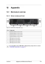
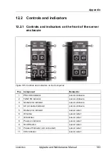
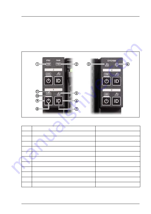
Figure 105: Controls and indicators on the front panel
Pos. Component
Related to:
1
PSU CSS indicator
server enclosure
2
FAN CSS indicator
server enclosure
3
Global error indicator
server enclosure
4
AC connected indicator
server enclosure
5
Global error indicator
server node 1
6
ID button
server node 1
7
ID indicator
server node 1
8
Power-on indicator
server node 1
9
On/Off button
server node 1
10
Power-off indicator (AC connected)
server node 1
11
CSS indicator
server node 1
Содержание PRIMERGY CX400 M4
Страница 6: ...Upgrade and Maintenance Manual CX400 M4 ...
Страница 126: ...126 Upgrade and Maintenance Manual CX400 M4 Hard disk drives HDD solid state drives SSD and 2 5 inch PCIe SSD ...
Страница 156: ...156 Upgrade and Maintenance Manual CX400 M4 Midplane kit ...
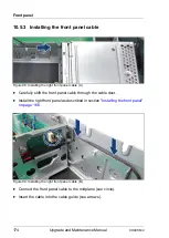
Страница 176: ...176 Upgrade and Maintenance Manual CX400 M4 Front panel ...
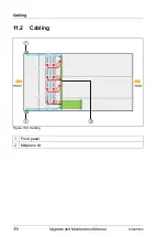
Страница 178: ...178 Upgrade and Maintenance Manual CX400 M4 Cabling 11 2 Cabling Figure 100 Cabling 1 Front panel 2 Midplane kit ...