


connected
to
it
and
set
the
enabling/disabling
setting
of
the
direct
I/O
function
of
the
PCI
expansion
unit.
In
this
case,
execute
the
setpciboxdio
command
to
set
the
enabling/disabling
setting
before
installing
it
on
the
physical
partition
by
executing
the
addboard
command.
When
you
have
changed
the
setting
of
the
direct
I/O
function,
do
not
restart
the
logical
domains
until
you
execute
the
ldm
add-spconfig
command
to
save
the
logical
domain
configuration
in
XSCF.
Note
-
Pull
out
all
the
PCIe
cassettes
with
the
PCIe
card
for
the
PCI
expansion
unit
to
be
installed.
After
incorporating
the
link
card
into
the
server,
attach
the
pulled-out
PCIe
cassette
to
the
PCI
expansion
unit.
Then,
install
the
PCIe
card
of
the
PCI
expansion
unit
on
the
server
by
using
PHP.
XSCF>
showboards
-p
0
PSB
PPAR-ID(LSB)
Assignment
Pwr
Conn
Conf
Test
Fault
----
------------
-----------
----
----
----
-------
--------
00-0
00(00)
Assigned
n
n
n
Passed
Normal
01-0
00(01)
Assigned
n
n
n
Passed
Normal
02-0
SP
Available
n
n
n
Passed
Normal
XSCF>
addboard
-c
assign
-p
0
02-0
PSB#02-0
will
be
assigned
into
PPAR-ID
0.
Continue?[y|n]
:
y
XSCF>
showresult
0
XSCF>
showboards
-p
0
PSB
PPAR-ID(LSB)
Assignment
Pwr
Conn
Conf
Test
Fault
----
------------
-----------
----
----
----
-------
--------
00-0
00(00)
Assigned
n
n
n
Passed
Normal
01-0
00(01)
Assigned
n
n
n
Passed
Normal
02-0
00(02)
Assigned
n
n
n
Passed
Normal
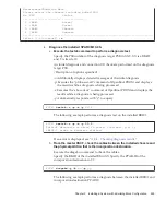
a.
Return
to
the
XSCF
shell,
execute
the
showboards
command,
and
check
the
system
board
(PSB)
status.
In
the
following
example,
system
board
02-0
is
in
the
system
board
pool.
b.
Execute
the
addboard
command
to
assign
the
system
board
(PSB).
The
following
example
assigns
system
board
02-0
to
physical
partition
0.
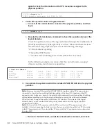
c.
Execute
the
showresult
command
to
confirm
the
end
status
of
the
previously
executed
addboard
command.
In
the
following
example,
0
is
returned
as
the
end
status,
so
the
execution
of
the
addboard
command
has
completed
correctly.
d.
Execute
the
showboards
command
to
check
the
system
board
(PSB)
status,
and
confirm
that
the
system
board
(PSB)
has
been
added.
13.
Start
the
physical
partition.
The
following
example
starts
PPAR#0.
Chapter
9
Installing
a
System
with
a
Building
Block
Configuration
259
Содержание M10 Series
Страница 1: ...Fujitsu M10 SPARC M10 Systems Installation Guide Manual Code C120 E678 12EN July 2015 ...
Страница 10: ...Fujitsu M10 SPARC M10 Systems Installation Guide July 2015 x ...
Страница 156: ...Fujitsu M10 SPARC M10 Systems Installation Guide July 2015 142 ...
Страница 169: ...A B Figure 4 14 Locations for passing cables between the racks Chapter 4 Configuring Building Block Connections 155 ...
Страница 176: ...Fujitsu M10 SPARC M10 Systems Installation Guide July 2015 162 ...
Страница 208: ...Fujitsu M10 SPARC M10 Systems Installation Guide July 2015 194 ...
Страница 240: ...Fujitsu M10 SPARC M10 Systems Installation Guide July 2015 226 ...
Страница 252: ...Fujitsu M10 SPARC M10 Systems Installation Guide July 2015 238 ...
Страница 290: ...Fujitsu M10 SPARC M10 Systems Installation Guide July 2015 276 ...
Страница 310: ...Fujitsu M10 SPARC M10 Systems Installation Guide July 2015 296 ...
Страница 336: ...Fujitsu M10 SPARC M10 Systems Installation Guide July 2015 322 ...
Страница 368: ...Fujitsu M10 SPARC M10 Systems Installation Guide July 2015 354 ...
Страница 374: ...Fujitsu M10 SPARC M10 Systems Installation Guide July 2015 360 ...