


DUAL port
DUAL
XSCF0...XSCF2
BB number
BB00...BB01
BB number
BB00...BB03
XSCF port number
BB00
DUAL
BB01
XSCF0
Figure
4-6
Connector
indication
example
of
an
XSCF
cable
4.3
Connecting
Cables
(for
Connections
through
Crossbar
Boxes)
For
connections
through
crossbar
boxes,
an
expansion
rack
is
shipped
with
the
SPARC
M10-4S
and
crossbar
boxes
mounted.
The
SPARC
M10-4S
and
crossbar
boxes
are
connected
by
crossbar
cables
(optical)
and
the
XSCF
units
are
connected
by
XSCF
cables
when
the
rack
is
shipped.
For
configurations
up
to
the
8BB
configuration,
skip
to
"
The
9BB
configuration
or
larger
requires
two
racks,
so
the
crossbar
cables
(optical)
and
XSCF
cables
that
pass
between
the
racks
need
to
be
connected.
For
any
subsequent
installation
expanding
to
the
9BB
configuration
or
larger,
the
connections
of
the
existing
crossbar
cables
(optical)
need
to
be
changed.
This
section
describes
how
to
connect
the
crossbar
cables
(optical)
and
XSCF
cables
that
pass
between
the
racks
and
how
to
move
crossbar
cables
(optical).
For
each
configuration,
provides
a
cable
connection
diagram
and
a
cable
list.
4.3.1
Changing
crossbar
cables
(when
subsequently
installing
expansion
rack
2)
When
subsequently
installing
expansion
rack
2,
you
need
to
change
the
connections
of
crossbar
cables.
This
work
is
not
necessary
during
the
initial
installation.
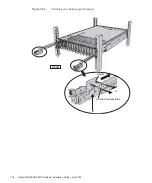
1.
Mount
a
crossbar
unit
in
XBBOX#80/#81.
a.
Remove
the
one
screw
(B
in
securing
the
blank
panel.
b.
Remove
the
blank
panel
(A
in
from
slot
#2,
where
the
crossbar
unit
is
to
be
installed.
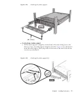
c.
Insert
the
crossbar
unit
into
slot
#2.
The
crossbar
unit
is
supplied
with
expansion
rack
2.
d.
Close
the
left
and
right
levers
of
the
crossbar
unit,
and
tighten
two
screws
(A
in
).
Fujitsu
M10/SPARC
M10
Systems
Installation
Guide
・
July
2015
148
Содержание M10 Series
Страница 1: ...Fujitsu M10 SPARC M10 Systems Installation Guide Manual Code C120 E678 12EN July 2015 ...
Страница 10: ...Fujitsu M10 SPARC M10 Systems Installation Guide July 2015 x ...
Страница 156: ...Fujitsu M10 SPARC M10 Systems Installation Guide July 2015 142 ...
Страница 169: ...A B Figure 4 14 Locations for passing cables between the racks Chapter 4 Configuring Building Block Connections 155 ...
Страница 176: ...Fujitsu M10 SPARC M10 Systems Installation Guide July 2015 162 ...
Страница 208: ...Fujitsu M10 SPARC M10 Systems Installation Guide July 2015 194 ...
Страница 240: ...Fujitsu M10 SPARC M10 Systems Installation Guide July 2015 226 ...
Страница 252: ...Fujitsu M10 SPARC M10 Systems Installation Guide July 2015 238 ...
Страница 290: ...Fujitsu M10 SPARC M10 Systems Installation Guide July 2015 276 ...
Страница 310: ...Fujitsu M10 SPARC M10 Systems Installation Guide July 2015 296 ...
Страница 336: ...Fujitsu M10 SPARC M10 Systems Installation Guide July 2015 322 ...
Страница 368: ...Fujitsu M10 SPARC M10 Systems Installation Guide July 2015 354 ...
Страница 374: ...Fujitsu M10 SPARC M10 Systems Installation Guide July 2015 360 ...