


Table
3-11
Dimensions
between
the
front
and
rear
columns
and
scale
positions
(continued)
Dimension
between
front
and
rear
columns
(mm)
Scale
position
730
2nd
720
3rd
710
4th
700
5th
690
6th
680
7th
670
8th
660
9th
650
10th
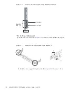
Note
-
If
you
have
difficulty
laying
a
thick
cable
into
the
cable
support,
move
forward
the
fixing
location
of
the
cable
support
to
make
the
work
easier.
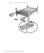
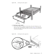
c.
Close
the
rear
door
of
the
rack,
and
confirm
that
the
cable
support
does
not
interfere.
If
the
cable
support
interferes
with
the
rear
door,
remove
the
cable
support.
Even
if
you
remove
the
cable
support,
leave
the
rails
secured
with
the
two
M6
screws
to
the
rack.
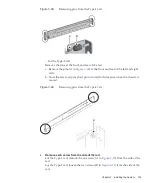
Figure
3-89
Completed
cable
support
attachment
Chapter
3
Installing
the
System
139
Содержание M10 Series
Страница 1: ...Fujitsu M10 SPARC M10 Systems Installation Guide Manual Code C120 E678 12EN July 2015 ...
Страница 10: ...Fujitsu M10 SPARC M10 Systems Installation Guide July 2015 x ...
Страница 156: ...Fujitsu M10 SPARC M10 Systems Installation Guide July 2015 142 ...
Страница 169: ...A B Figure 4 14 Locations for passing cables between the racks Chapter 4 Configuring Building Block Connections 155 ...
Страница 176: ...Fujitsu M10 SPARC M10 Systems Installation Guide July 2015 162 ...
Страница 208: ...Fujitsu M10 SPARC M10 Systems Installation Guide July 2015 194 ...
Страница 240: ...Fujitsu M10 SPARC M10 Systems Installation Guide July 2015 226 ...
Страница 252: ...Fujitsu M10 SPARC M10 Systems Installation Guide July 2015 238 ...
Страница 290: ...Fujitsu M10 SPARC M10 Systems Installation Guide July 2015 276 ...
Страница 310: ...Fujitsu M10 SPARC M10 Systems Installation Guide July 2015 296 ...
Страница 336: ...Fujitsu M10 SPARC M10 Systems Installation Guide July 2015 322 ...
Страница 368: ...Fujitsu M10 SPARC M10 Systems Installation Guide July 2015 354 ...
Страница 374: ...Fujitsu M10 SPARC M10 Systems Installation Guide July 2015 360 ...