


Chapter 8
Appendix 2. Effect on Insulation of General-purpose Motor Driven with 460V Class Inverter
8-11
8
Appendix 2. Effect on Insulation of General-purpose Motor Driven with 460V Class Inverter
Introduction
When an inverter drives a motor, surge voltages generated by switching the inverter elements are superimposed on the inverter
output voltage and applied to the motor terminals. If the surge voltages are too high they may have an effect on the motor
insulation and some cases have resulted in damage.
For preventing such cases this document describes the generating mechanism of the surge voltages and countermeasures
against them.
2.1 Operating principle of inverter
2.1.1 Main circuit configuration of inverter
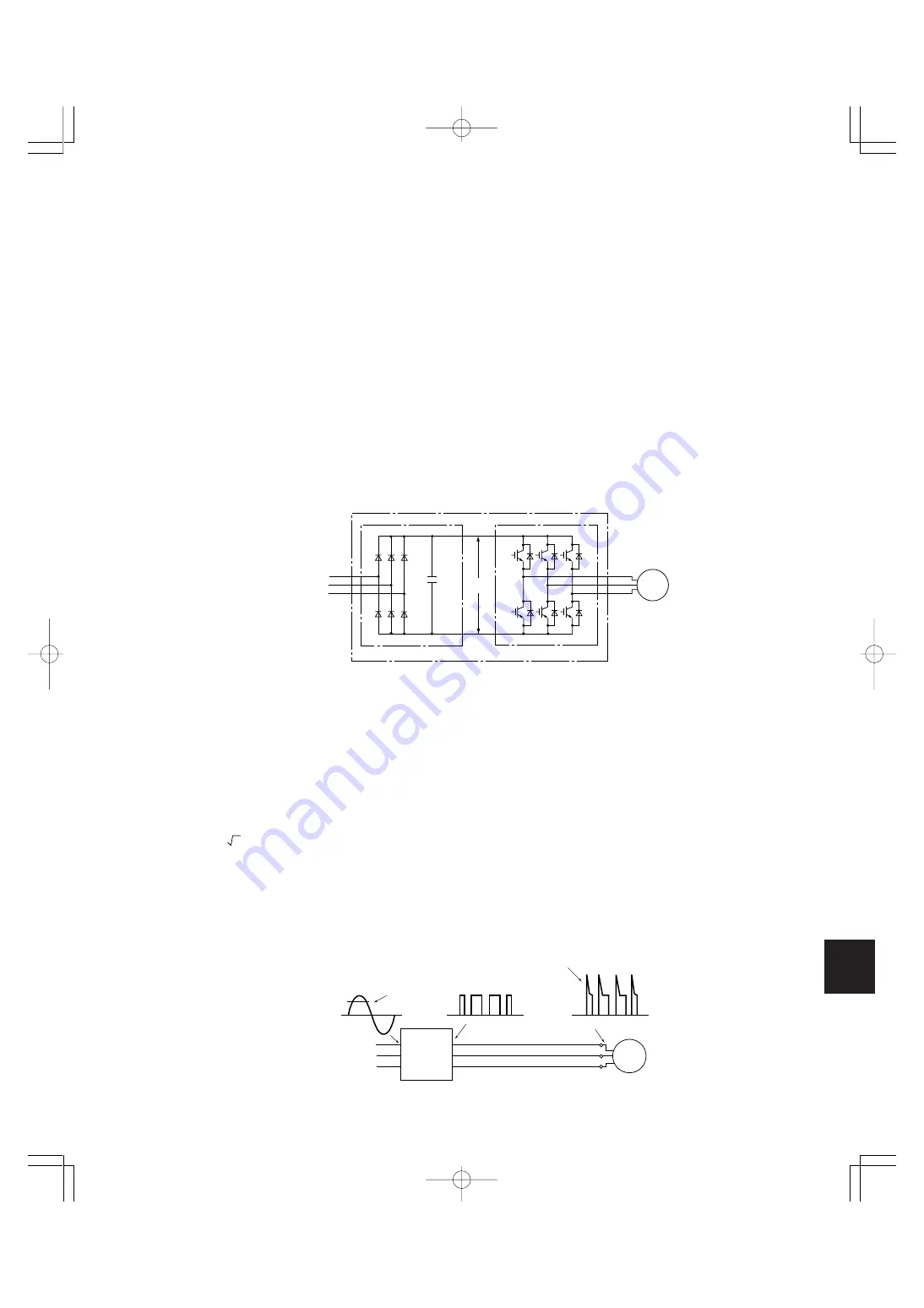
The main circuit of an inverter is configured with a converter part and an inverter part. The former part rectifies a commercial
power source voltage and eliminates resulting ripple components, and the latter part converts DC voltage to AC voltage through
a 3-phase bridge circuit composed of switching elements like transistors. (Refer to Fig. 1)
2.1.2 Control method of inverter
The PWM (Pulse Width Modulation) control is commonly adopted in general-purpose inverters. This method generates multiple
switching pulses in one output cycle because both the output voltage and frequency are simultaneously controlled in the inverter
part. The output voltage control is carried out by varying the pulse width while the pulse magnitude is kept constant.
The number of switching pulses generated in one second is designated as a carrier frequency and is normally high up to 0.7 to
16kHz. So transistors capable of high-speed switching (IGBT, etc.) are used for inverter elements.
2.2 Generating mechanism of surge voltages
As the inverter rectifies a commercial power source voltage and smoothes into a DC voltage, the magnitude E of the DC voltage
becomes about
2
times of that of the source voltage (about 620V in case of an input voltage of 440V AC). The peak value of the
output voltage is usually close to this DC voltage value.
But, as there exists inductance (L) and stray capacitance (C) in wiring between the inverter and the motor, the voltage variation
due to switching the inverter elements causes a surge voltage originating in LC resonance and results in the addition of a high
voltage to the motor terminals. (Refer to Fig.2)
This voltage sometimes reaches up to about twice of the inverter DC voltage (620V x 2 = about 1,200V) depending on a switching
speed of the inverter elements and a wiring condition.
Excerpt from Technical Document of
the Japan Electrical Manufacturers’
Association (JEMA) (March, 1995)
Motor
Inverter part
Converter part
Commercial
power source
Inverter
E
+
Fig. 1 Main circuit configuration of inverter
Fig. 2 Voltage wave shapes of individual positions
440V AC
620V DC
Surge voltage
Motor
Inverter
Commercial
power source
Chapter8-2(P11˜13).p65
07.8.9, 12:57
Page 11
Adobe PageMaker 6.5J/PPC
Содержание FRENIC5000G11S Series
Страница 1: ......
Страница 2: ......
Страница 154: ...3 30 3 12 13 P23 30 65p 07 8 9 12 34 Page 30 Adobe PageMaker 6 5J PPC...
Страница 166: ...4 12...
Страница 182: ...3 12 13 P23 30 65p 07 8 9 12 34 Page 30 Adobe PageMaker 6 5J PPC 5 16...
Страница 212: ...3 12 13 P23 30 65p 07 8 9 12 34 Page 30 Adobe PageMaker 6 5J PPC 6 30...
Страница 234: ...MEMO Chapter8 4 P15 p65 07 8 9 12 57 Page 18 Adobe PageMaker 6 5J PPC...
Страница 235: ......
Страница 236: ......


