M6500 Series NE Configuration Manual
138
The lower middle area is the display section of the current alarm. From left to right in turn, the table header is:
check box, serial number, alarm level, NE, alarm source, alarm name, alarm type, status, generation time,
clearance time, confirmation status, confirmer and confirmation time, operation.
Check box is used to check or cancel a specified alarm, or the first check box can be used to select all
the alarms on the page.
The serial number is the number of the alarms, sequentially increasing from 1.
There are four alarm levels, marked by different colors: emergency level (red), main level (orange),
secondary level (blue), warning level (cyan).
Network element is the IP of network equipment that generates alarm.
The alarm source is the specific slot or port information of NE which generates alarm.
Alarm name, alarm type, status, generation time, clearance time, confirmation status, confirmer and
confirmation time are relatively simple, we will not go into much detail here.
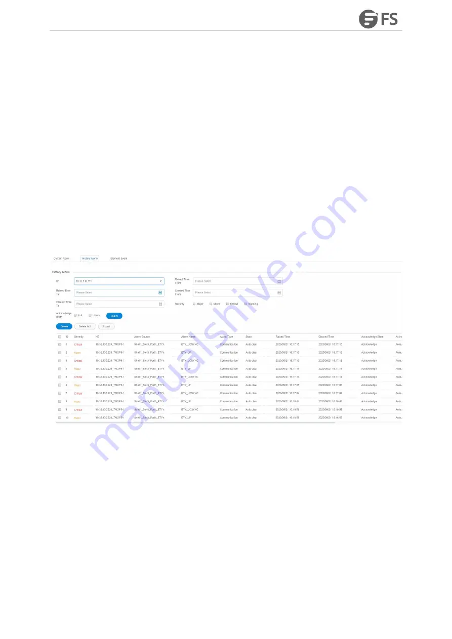
8.2.2. History Alarm
Click on
“
History Alarm
”
in the submenu to enter the history alarm page, as shown in the figure below:
Figure8-16 History Alarm
The lower right corner of the history alarm interface can filter the number of alarms displayed on the current
page, and the number of displayed alarms per page can be adjusted to 10, 20, 50 and 100.
The Filter, All, Delete, Delete All, Export buttons are shown in the right area of the navigation bar.
Functions of“
Query
”buttons are the same as the functions of those buttons in the current alarm.
The function of“
Delete
”button is to delete the selected history alarm, as shown in the following figure.
Содержание M6500 Series
Страница 12: ...M6500 Series NE Configuration Manual 11 Figure 1 3 Start NMS Server...
Страница 63: ...M6500 Series NE Configuration Manual 62 Figure 4 34 Parameter Reading of WDM CFP2 Optical Transceiver...
Страница 105: ...M6500 Series NE Configuration Manual 104 Figure5 80 Site to Site Primary and Standby Protection Environment...
Страница 109: ...M6500 Series NE Configuration Manual 108 Figure6 5 TP Multiplexing Configuration Step 2...
Страница 113: ...M6500 Series NE Configuration Manual 112 Figure6 12 Set Line Side PM Overhead...
Страница 116: ...M6500 Series NE Configuration Manual 115 Figure6 16 Configure Line Side Port TTI...
Страница 117: ...M6500 Series NE Configuration Manual 116 Figure6 17 Configure Client Side Local End Port TTI...
Страница 118: ...M6500 Series NE Configuration Manual 117 Figure6 18 Configure Client Side Opposite End Port TTI...
Страница 129: ...M6500 Series NE Configuration Manual 128 Figure7 10 Select Protection Mode...
Страница 138: ...M6500 Series NE Configuration Manual 137 Figure8 14 Alarm Details Figure8 15 Alarm Document Link...


